
Description
The purpose of the study was to observe the effects of rapid changes in IOP in a 3-5-day-old piglet model. A custom indentation device was constructed to allow for different indentation depths and rates to achieve this purpose.
In order to evaluate rapid changes in IOP as a cause of RH, the eyes of immature 3-5-day-old piglets (n=4) were subjected to a series of eye indentations. To test conditions similar to ODR, a single indentation to depths ranging from 1-7 mm was performed at two indentation rates (1 mm/s and 50 mm/s). A cyclic indentation was also performed at 3 Hz for 30 seconds to the same depths as the single indentation portion of the study. The 3 Hz frequency was chosen to match the frequency of shaking reported in surrogate studies recreating abusive scenarios [9]. IOP was monitored continuously throughout the indentations with a fiber optic pressure transducer (Samba Preclin 420 LP, Gothenburg, Sweden).
In order to achieve systematic and repeatable indentation depths and rates, a computer controlled indentation device was designed and constructed. The indentation device was capable of indenting between 0 and 7 mm. It could perform single “indent and hold” tests as well as repetitive indentations at 3 Hz. The device was small enough to easily move around a surgical table. Force and displacement instrumentation were included to correlate the indentation depth and eye contact force with the resulting IOP.
The actuation of the indenter was created by attaching a rack and pinion (Stock Drive Products, New Hyde, NY) to a stepper motor controlled by an Arduino (Uno R3, IDE 1.0.5, Italy) microcontroller. Connected to the rack was a 10 lb force transducer (LSB200, Futek, Columbus OH) which attached to a 4 mm diameter stainless steel tip.
The indentation tip was flat with rounded edges to contact the eye uniformly without damaging the sclera. A linear variable differential transformer (LVDT) (Transtek 240 series, Ellington, CT), was attached to the nonindentation side of the rack to accurately measure the indentation depth (Figure 20). Data from the fiber optic pressure sensor, LVDT, and force transducer were continuously collected at 300 Hz using a data acquisition system (National Instruments NI 9201, Austin, TX), and stored on a Dell (Round Rock, TX) laptop.
The indentation device was equipped with its own power supply and circuitry to regulate voltage for the Arduino, LVDT, and stepper motor. A stepper motor driver board (Big Easy Driver, Sparkfun, Boulder, CO) powered and controlled the stepper motor. Custom Arduino code with a simple user interface was created to control the rate, direction (forward and backward), and depth of the indentation tip.
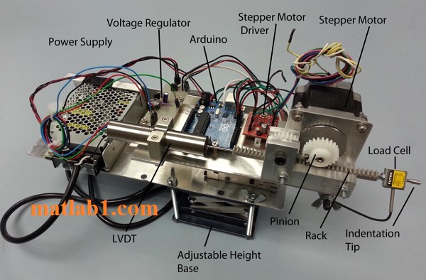
Indentation device designed to apply compressions to the eye at variable
The device was equipped with a locking hinged bracket to adjust the angle at which the indentation occurs. A fine threaded screw was included to allow precision advancement of the indentation tip. The whole assembly was mounted to an adjustable base to facilitate use at different heights.
MATLAB and microcontroller code for controlling air conditioner

Shray –
Quite Professional.