
Description
The software design using two Freescale 1321X-SRB’s involves creating three separate programs that communicate with each other in one way or another.
Two of the programs are for each of the 1321X-SRB’s, as each will be performing different tasks and communicating differently, while the third is a PC application that will communicate with the microcontroller connected to the PC.
For the design mentioned beforehand, the 1321X-SRB connected to the PC is in a way the middle-man between the PC and remote microcontroller board.
The primary purpose of the remote microcontroller is to gather sensor data and control lighting and air conditioning, while the PC application will be capable of displaying data collected by the remote board, while adding the functionality of controlling the air conditioner.
Freescale’s Code Warrior and their SMAC based software is used to program the two boards, while MATLAB” is utilized to create a GUI and program to communicate with the boards over USB.
Remote Microcontroller
The remote 1321X-SRB powered either by batteries or a DC power adapter is where much of the home automation features are put to use. This includes the proximity sensing, current sensing and load control, ambient light and temperature monitoring, as well as air conditioner control. There are multiple ways to go about programming the microcontrollers. Instead of constantly transmitting collected sensor data to the PC connected microcontroller, the data is only transmitted upon request, as seen in Figure 1.
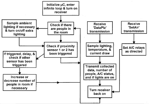
Remote Microcontroller Software Flowchart
As shown in the flowchart, the microcontroller is checking the proximity sensors most of the time, as they are set up in a polling interrupt manner. If one of the proximity sensors triggers the interrupt flag, the other sensor is checked after a short delay to see whether a person entered or left the room. The microcontroller is always keeping track of how many people are in the room, and if there is at least one person, the ambient lighting is checked as well. If necessary, the lighting is turned on as well, and if the room ever gets very bright again or there are no people in the room, the lighting turns off. As mentioned, data is only transmitted upon request, and the microcontroller responds by sampling the ambient lighting, temperature, and current draw. To achieve better accuracy, the sensors are sampled multiple times and averaged. The data is then transmitted to the other 1321X-SRB connected to the PC, along with other information such as the number of people in the room and the status of the relays. Similarly, when this remote microcontroller receives a request to set the air conditioner, the relays are configured as desired. The next time sensor data is transmitted, the status of the relays will show if the air conditioner is set appropriately. The core program code for the remote transceiver can be found in this project. Programming the complimentary 1321X-SRB is done similarly, however communication will take place between both the remote microcontroller as well as the PC.
PC Connected Microcontroller
The second transceiver is connected to the PC, receiving power over the connected USB cable and communicating to the PC through it as well. As mentioned previously, this microcontroller’s main function is to relay data back and forth from the PC and the remote transceiver. If necessary, multiple sensors can also be connected to this board as well. The program functions similarly to the remote microcontroller’s, however instead of awaiting a signal over the air, the program checks to see if there was any incoming string from the PC, as shown in the flowchart below. As can be seen, the program acts depending on what the PC transmits. There are six possible character strings the microcontroller checks for from the PC. Receiving a ‘D,’ the microcontroller follows by asking the remote microcontroller for the sensor, relay, and other data. The receiver is turned on for a few seconds to allow the remote microcontroller to gather data, and if the data is received successfully, the PC connected microcontroller samples its own temperature as well to transmit two separate temperature values along with all the other data to the PC as one long string. If the microcontroller receives an ‘O,’ T,’ ‘G,’ or ‘Y’ from the PC however, the microcontroller makes note of what air conditioner setting the PC requests. This is usually followed by an ‘S’ string from the PC, in which the microcontroller then transmits the desired A/C setting to the remote microcontroller to toggle the appropriate relays. To guarantee that the A/C was set properly, the data is also requested from the remote microcontroller, as the data will contain the status of all the relays. As with the previous program, the main software code used for the PC connected microcontroller is available in this project. With the two microcontrollers programmed as described, it is then possible to use a suitable PC application that will make use of the two transceiver boards.
PC Application
The PC programming was done using MATLAB®, creating a graphical user interface that assists in communicating with the PC connected microcontroller.
Simplifying the implementation of the program, Figure 2 shows the basic outline of how the software functions. The first steps involve initializing any variables, opening the user interface figure, as well as connecting to the microcontroller. To gather data, a countdown is used to request the collection of sensor and other information at certain intervals. The data is gathered transmitting the string ‘D’ as described previously, and the data is also gathered any time the air conditioner is set differently. The program will update the display with all of the relative data regarding sensors and A/C status on screen.

Much of the programming is geared towards controlling the air conditioner with a custom programmed thermostat. This is likely the most complex part of the programming, as it is also necessary to make sure the software does not allow the air conditioner condenser to turn back on too rapidly had it just been on. As relay data is gathered every time the air conditioner is set differently, it is possible to determine whether or not it is correctly set, and whether the signal needs to be retransmitted. Lastly, if the PC is currently in control of the air conditioner when the user tries to close the program, the PC try to turn off all relays to hand control back over to the standalone thermostat. While the overall setup can be described using the flowchart above, much of the programming resides in the graphical user interface.
https://www.build-electronic-circuits.com/microcontroller-programming/
Reviews
There are no reviews yet.