
Description
To make TOF measurements, an avalanche photodiode (APD) (C12702, Hamamatsu) and a fold mirror were added to the optical setup as illustrated in the schematic in Fig. 1 (a). A 3D printed mount to reduce cross-talk between transmitting and receiving optical passes was also added as illustrated in Fig. 1 (b).
As illustrated in Fig. 1 (a), the laser pulse travels from the collimating objective through an adjustable aperture and is directed by a fold mirror onto the DMD at a 30º incident angle.
The reflected light retraces this path through the DMD to the APD. The entire physical optical setup of the LIDAR system is shown in the photograph in Fig. 2.
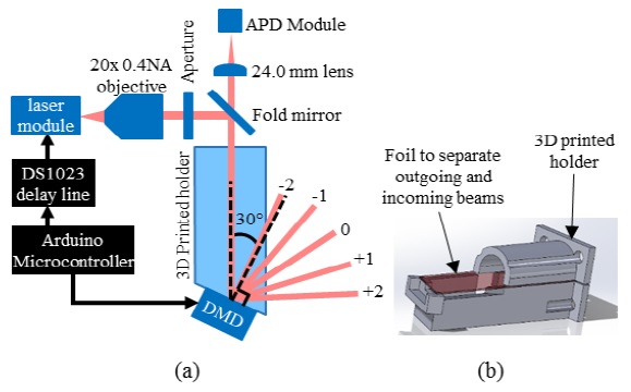
Fig. 1. Illustrations of (a) the optical setup used in 1D linescan LIDAR system and (b) the optical isolation scheme.

Fig. 2. Photograph of complete optical LIDAR setup.
http://ecars.inoe.ro/wp-content/uploads/2016/05/ECARS_2016_vf_optics_ver1.pdf
Reviews
There are no reviews yet.