
Description
Building the Zoetrope Pedestal
The pedestal design was fairly simple to start. I designed a circular plate that the zoetrope would sit upon and that would attach to a motor shaft using a small screw. I hired a machinist to mill a sturdy plate out of aluminum that could handle the weight of any zoetrope, but it would itself also be lightweight when attached to a spinning motor. This would prevent potential warping of the plate and guarantee stability. The plate also was fitted with a ¼” screw on top to allow for tightening to secure the zoetrope and for registration alignment during animation.
The plate could attach to the shaft of a 12VDC, 0.166A Gearhead Motor34 or a 1.8°, 12VDC, 0.4A Stepper Motor35 depending on need – these were the motors I purchased for this project. The DC motor utilized a very simple setup where the terminals connected to an AC to DC Power Supply36 and the rotation speed was controlled by turning the power up or down, but being careful not to exceed the 12VDC limit of the motor. This motor provided great torque; however, it was not precise. The stepper motor on the other hand needed a bit more than a power supply.
Stepper motors were built with two sets of coils, typically including center-taps. The permanent-magnet rotor required the coils to be energized in a precisely timed order to step in one direction or the other. Each coil either had a negative and positive lead, or a negative, positive and ground lead depending on the requirement for the application. DC motors also had permanent magnets, but with a single coil in the rotor, typically just a negative and positive lead setup. To turn a DC motor, you simply energized the coil by applying a voltage to the two leads. Because stepper motors have more leads, they require a controller or driver to run.
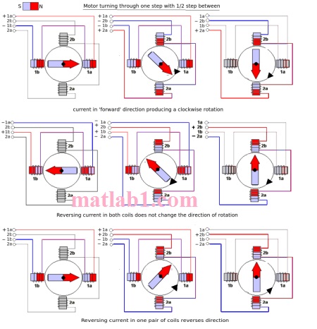
Stepper motor coils energizing in sequence per step
Most of the filming utilized the stepper motor because of the ability to reliably turn it to a fairly accurate and consistent position. In order to make this happen, I used an Arduino Uno R3 Board38 with an Adafruit Motorshield V239 to control the rotation speed and precision of the stepper. I wrote code and used a breadboard with buttons to allow for full-steps and microstepping40, both forward and reverse, along with a button to release the motor. Since some of the zoetropes were fairly large, a lot of torque and power was needed to turn a stepper to both move the shaft beyond the initial inertia, and find the right accelerated speed to handle the reflected inertia when spinning.

Arduino setup with prototyping board utilizing programmable buttons
Reviews
There are no reviews yet.