Isomorphic Sensing
In Greek, the word isomorphic loosely translates to \equal in form.” Traditional sensors perform isomorphic sensing. In the context of this dissertation, an isomorphic sensor is any sensor which attempts to produces measurement data that resembles the signal-of-interest. In this paradigm, the analog instrument, sampling scheme, and post-processing algorithms are separate components and processes. I will discuss three important examples of isomorphic sensors: the pinhole camera, the photographic camera and the optical spectrometer1. These sensors have inspired many other optical and non-optical sensors throughout history, so it is natural to use them as examples for comparison when discussing computational sensing. Before I continue, I want to dene measurement because it can often be used in
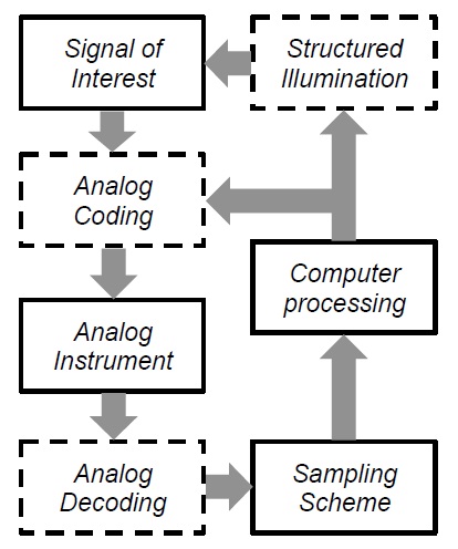
Figure 1.2: In a computational sensor, coding, decoding, and structured illumination are used in addition to the analog instrument, the algorithms, and sampling scheme. The dashed boxes represent optional processes that may or may not be needed.
an informal manner. In this dissertation a measurement has a very specic meaning. A measurement is a process that converts a physical phenomena to a collection of data. The signal-of-interest is the physical phenomena that one is interested in quantifying. I will call the collection of data the measurement data. The word sensing has a less precise meaning and I will use it in an informal manner. Sensing is any act that uses techniques, instruments, or processes that produces measurement data. In the photographic camera, the signal-of-interest is the intensity distribution of the object. The analog instrument consists of the lenses which are designed and fabricated to produce an image that looks like the object at the FPA. The better the optics the more the image resembles the object. The FPA then samples the image and produces a digital representation of the intensity distribution of the object, the measurement data. If one is interested in performing a task such as detection or classication, the measurement data is sent to a post processing algorithm to perform those tasks. There are two major sub-systems in the photographic camera which determine how well it performs: the optics and the FPA. Ideally, the optics (the analog instrument in this case) will produce a point-spread function (PSF) which is at the physical limit set by diffraction given the aperture size. For example, in a task such as the detection of a star from several neighboring stars in the night sky, if the PSF is much larger than the center to center seperation of the two stars in the optical image, it will be difficult to detect. Even if the PSF is small enough, the FPA must sample at a ne enough pixel-to-pixel spacing, called the pixel pitch, to accurately reproduce the intensity variations at the scale which is pertinent to the task. Intuitively, this makes sense because if the stars are imaged onto a single pixel, then one cannot ever hope to be able to accurately the detect the star without some other prior or side information. The pinhole camera consists of a small hole and a box which prevents any light except from the pinhole from entering, see Figure 1.3. The pinhole camera is useful for imaging in parts of the electromagnetic spectrum and particles for which there is no direct analog to the refractive lens or re ective mirror. Like the photographic camera, the smaller the PSF diameter, the better the spatial resolution. Unfortunately, in the traditional pinhole camera, the only way to reduce the PSF diameter

Figure 1.3: A pinhole camera is a simple imaging system that forms an image without a lens or mirror. This is due to the ray nature of light. A small hole will only admit a small amount of rays from an object point that is radiating light. Each point on a object emits light at different angles, and the image formed is a superposition of different rays. The smaller the hole, the less blurry the image. However, small holes also limit the amount of light is by decreasing the diameter of the pinhole which reduces the amount of light.
is by decreasing the diameter of the pinhole which reduces the amount of light. In the spectrometer, the signal of interest is the spectrum of the object. The optics are designed to take the incoming light and separate various wavelength components, see Figure 1.4. The part of the spectrometer which is used to physically solate the wavelengths is called a monochromator. The monochromator contains a prism or diffraction grating which creates a wavelength dependent angular seperation. The result is a spectral intensity as a function of position at the FPA. The FPA and post-processing algorithms are used in the same manner as the photographic camera, which is to sample the spatially varying intensity (which is now encoding spectral information) creating a digital version of it and to perform various tasks on the measurement data. For now, I will concentrate on the slit spectrometer, which measures the spectrum at a single spatial location on the object. In the spectrometer, one of the important performance metrics is spectral resolution, which I denote . The spectral resolution is the smallest difference in wavelength the instrument can discern. Large spectral resolutions can degrade the spectrometers ability to discern important parts of the spectrum. Similarly with the camera, the FPA must have a pixel pitch which is small enough to correctly sample the variations in the spectrum. The point-by-point nature of isomorphic sensing is both a strength and a source
Figure 1.4: An isomorphic slit spectrometer with a 4F conguration. The slit limits the lateral extent of the object (or intermediate image). The light from the slit is collimated and separated into different angles based on the wavelength. A second lens then images wavelength shifted copies of the slit on the image plane where the detector is. As the slit size decreases, less light is allowed, but one gains spectral resolution by rejected light from neighboring locations on the object.
of weakness. The strength comes from the straightforward and intuitive architecture of the isomorphic sensor. Each subsystem: the optics, the focal-plane array (FPA), and the post-processing can be designed and constructed separately as long as they meet their individual specications. As long as the signal-to-noise ratio (SNR) is sufficient and the sampling rate is high enough, one is guaranteed to recover the signal. One of the weaknesses of the isomorphic approach is the ability to measure low SNR signals. Because the signal-of-interest is sampled in a completely point-by-point at each exposure, each pixel indepdently contributes a certain amount of noise. If the noise dominates, the measurement delity decreases, forcing the operator to increase the exposure time. For weak signals, the exposure time can become prohibitive and for temporally dynamic signals this leads to a loss of temporal resolution. Indeed, one of the major engineering trade-os faced by traditional spectrometer designers is that when one attempts to increase the light collection (increased slit-width) the spectral resolution degrades. Similarly, in the pinhole camera, there is a throughput versus spatial resolution trade, increasing the size of the pinhole degrades the PSF. It would be easy to assume that recent progress in machine learning and statistical signal processing combined with the dramatic increase in computing power that one could simply post-process poor measurements and obtain useful data. However, this is not possible due to the an important theorem in information theory called the data processing inequality. The information content of a signal cannot be increased through post-processing. Another weakness of isomorhic sensing is that the seperation of the analog instrument, the sampling scheme, and the data processing algorithms lead to increased size, weight and power-cost (SWAP-C). As I mentioned in the photographic camera, the optics must be designed to produce a small PSF. For demanding applications, the optical design and fabrication can be the most expensive component of the sensor. While the price of FPAs sensitive to the visible wavelength region have fallen, FPAs sensitive to certain parts of the electromagnetic spectrum can be quite expensive or non-existant .In many cases, the signal is redundant and high resolution sampling becomes a waste of resources, such as data storage and communications bandwidth. A good example is in photography where often the post-processing takes the digital image and applies a compression algorithm which looks for patterns in the signal and reduces the le size, discarding much of the sample data. The isomorphic sensor approach has served humanity well, however with all the weakness that I have discussed, there is a need for sensors which can operate in low- SNR conditions, with fewer measurement time, fewer measurements, or at lower SWAP-C while still producing useful information relavent to the sensor task. I will now begin to discuss some of major techniques in computational sensing that can be used to address some or all of the issues that I just stated.