
Hand Anatomy
The hand is responsible for nearly 90% of upper limb function. A large number of joints and bones provide the motion capabilities of the hand[8]. The hand has 27 bones, and the fingers are labeled digits 1-5, with the thumb as digit 1, and the little finger as digit 5 (seen in Figure 1). Every finger is connected to the palm with metacarpophalangeal (MCP) joints. The MCP joints allow flexion-extension as well as a slight degree of axial rotation. The MCP joint of the thumb allows approximately 75-80° of flexion, while the second through fifth MCP allows for about 90°. Active extension at these joints is 25-30°. Approximately 20° of abduction-adduction is allowed at the MCP. However, the abduction-adduction movements of the MCP joints are restricted in flexion. The interphalangeal (IP) joint is a hinge joint provides flexion and extension movements of the finger. The thumb has one interphalangeal joint, and each of the second through the fifth digits has one proximal interphalangeal (PIP) joint and one distal interphalangeal (DIP) joint. About 110° of flexion are allowed at the PIP joints and 90° at the thumb IP joint. Extension reaches 0° at the PIP and 25° at the thumb IP joint. The motions available at the DIP joints consist of nearly 90° flexion and 25° extension.
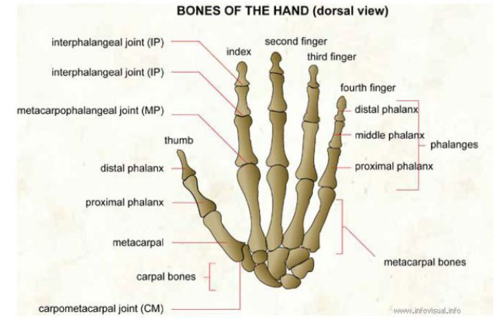
Figure 1 Bones of the Hand
Grasping is one of the main functions and movements of the hand. Grasps can be classified based on power and precision movements. People use different numbers of fingers to grasp an object depending on the size of the object. During the grasping, the thumb could be always separated from the other fingers to form a jaw [10, 11]. Joint compressive forces at the MCP, PIP, and the DIP joints of the index fingers during isometric hand functions are presented in Table 1.

Figure 2 Main Functions and Movements of the Hand
Table 1Joint Compressive Force (N) for Various Hand Functions
Hand Rehabilitation Devices
Much work has been done in the area of hand rehabilitation devices. There are two main groups of upper limb robotic systems classified by mechanical characteristics: the exoskeleton and operational machines/ end-effectors. Several existing products will be presented in this study. Interactive Motion Technologies, Inc (Watertown, MA) sells a hand robot mounted on a companion planar robot (MIT-Manus). The MIT-Manus allows 2 active DOFs at the shoulder and the elbow, while the InMotion Hand is optional module mounted senses grasping forces. A software platform is developed to provide exercise games for patients. However, the hand module only allows 1 DOF motion. Therefore, it could not capture information from each finger.
Figure 3 The InMotion Robot. LEFT: InMotion Hand Robot RIGHT: InMotion Arm Robot and the
mounted InMotion Hand Robot
The University of California, Irvine developed a hand-wrist assisting robotic device (HAVARD) to assist functional grasping and releasing movements for stroke patients. The device is actuated by pneumatic cylinders, and it provides 3 DOFs for thumb, fingers, and wrist. The range of motion (ROM) of the MCP joint is about 25° to 90°, and 20° extension to 15° flexion at the wrist. However, pneumatic actuation system is complex and expensive.
Figure 4 the Hand-Wrist Assisting Robotic Device (HWARD)
Compared with end-effectors, the exoskeleton could carry with patients. Therefore it could help patients to perform rehabilitation exercises at home. There are a lot of hand exoskeletons with various structures. Linkage mechanisms and cable-driven mechanisms are widely adopted in existing hand exoskeletons. Figure 5 is an application of hand exoskeleton using four-bar linkage mechanisms. The device is developed by the Harbin Institute of Technology, China. Each finger elements are driven by a brushless motor, and the maximum output force is up to 8N. However, these types of exoskeleton are very complicated. The linkage mechanisms will increase the weight and the size. In addition, building this type of exoskeleton is very expensive.
Figure 5 Hand Exoskeleton using Four-bar Linkage Mechanisms
Cable-driven mechanism is another widely used structure in existing hand exoskeleton products. Saebo, Inc sells a type of cable-driven hand exoskeleton (the SaeboFlex) for stroke rehabilitation (as seen in Figure 6). The advantage of cable-driven mechanism is that this mechanism is lightweight and low cost and easy to adjust to customized hand geometry. The disadvantage is that the cable works only in traction, there for a couple of cables should be implemented for both flexion and
extension. Also, the resistive force in SaeboFlex is generated by one spring. Therefore, force distribution within DIP, PIP, and MCP joint is uncontrollable.
Figure 6 The SaeboFlex Exoskeleton
Rapid Prototyping Techniques
There are unique challenges in designing and manufacturing rehabilitation devices for patients. Variation in the biomechanical properties of the patients leads to various design requirements. In addition, customized rehabilitation devices are small batch products. Therefore, the traditional mass manufacturing process is difficult and expensive to fabricating personal rehabilitation devices. Rapid prototyping techniques (also known as “Addictive Manufacturing”, “3D Printing”, and “Layered Fabrication”) is a fast, accurate, and cost-effective way to fabricate complex parts. It is uniquely suited in biomedical fields. In the rapid prototyping process, parts are built in vertical layers. At each point on the z-axis, it deposits structural material at the desired location. In order to create complex shapes, support materials will be filled in the gaps where there is no part material. After the
material is solidified then the machine can move to build the next layer. The drawbacks of the current rapid prototyping techniques are the cost and the strength of the material. Since the parts are built layer by layer, the strength of the 3D printed parts are not as strong as ones fabricated by traditional manufacturing processes. Also, the time and the cost of the 3D
printed parts are higher than traditional ways in mass fabrication tasks. A combination of rapid prototyping techniques and traditional manufacturing processes will make the rehabilitation devices much cheaper and personal.