Three-Dimensional Printing
3D printing is a promising technology for regenerative medicine because it allows customized structures to be fabricated ranging from acellular bone-tissue scaffolding to cellladen vascularized hydrogels. To fabricate structures, this technique uses a computer aided design (CAD) of the desired structure to digitally ‘slice’ it into two dimensional (2D) crosssections of defined thickness, which are then delivered to the printer to iteratively build a 3D structure. A defining feature of 3D printing is the ability to fabricate structures with overhanging features, meaning structures like porous bone can be physically duplicated. A variety of printing techniques are currently in use for tissue engineering, the three most prominent being selective laser sintering (SLS), polymer extrusion or fusion deposition modeling (FDM), and stereolithography (SLA).
Selective Laser Sintering (SLS)
Selective Laser Sintering (SLS) solidifies a powder via heat from a scanning focused laser. A new layer is printed when the powder bed platform moves down and a recoater arm moves fresh material from a powder supply reservoir into the vacant printing region, as shown in Figure 1 SLS is a useful technique to print structures of stiff (~GPa) material that cannot be readily fabricated using traditional techniques (e.g., injection molding is unable to fabricate a porous, metal scaffold for bone regeneration). Overhanging features are naturally supported by the unexposed powder bed. Conversely, because this technique uses a powder material, surface-roughness is dependent on the powder particle size, which leads to part failure in highfriction environments (e.g., joint structures). Additionally, many biomaterials cannot be sintered from powder form.
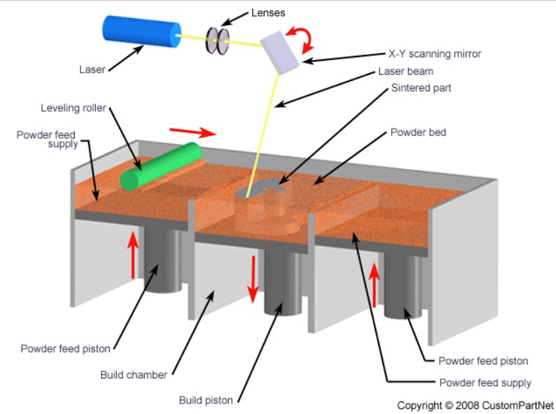
Schematic of SLS where a cross-section of the desired 3D structure is sintered in the powder bed, the build chamber then moves down, the recoater arm or levelling roller pushes a new supply of powder into the chamber for the next cross-section to be sintered. (adapted from Verma et al.).
Fused Deposition Modeling (FDM)
FDM is currently the most widely used 3D printing technique in regenerative medicine, so much so that the community uses the term ‘inkjet’ or ‘bioprinting’ exclusively for this printing process. FDM uses either a series of nozzles or filaments to deposit material onto a substrate from above where, again, a 2D section of the 3D structure is built up by scanning the print head (Figure 2). FDM, also referred to as polymer extrusion, is an appealing technique to fabricate synthetic biological tissues due to its ability to print multiple cytocompatible soft materials in a single structure. However, to date there have been no structures fabricated with both stiff (~1-100s MPa) and soft regions (~10s-100s kPa) in a single print. The barrier, which is a focus of this work, is that stiff, cytotoxic material diffuses into the soft, hydrated material.
Materials in FDM must be shear-thinning to be extruded. Shear-thinning, thixotropic materials behave as a liquid when a force is applied (i.e., as the material is extruded) and then behave as a solid when the shearing force is removed. This requirement constrains the range of useful materials to a subset of liquid polymers and is currently the subject of substantial academic and industrial research. The pressure to deposit material can also reduce cell viability, therefore the printing speed is constrained by the amount of pressure a given cell line can sustain. The extrusion nozzle is an additional constraint because it limits the minimum feature size and resolution of the printed structure to approximately two-times the tip diameter (>10μm).

Figure 2 Schematic of two types of FDM processes, where inkjet utilizes thermal or piezoelectric control of material deposition and robotic dispensing requires an external force to deposit material through a nozzle-based system (adapted from Malda et al., 2013).
Stereolithography (SLA)
SLA was the first demonstration of 3D printing, invented by Chuck Hull in 1983. This method uses a photo-curable liquid resin and an exposure source (laser or programmable mask) to solidify 2D cross-sections of a desired structure. Translating the sample stage axially allows fresh material to flow into the vacated patterning region, where a new layer is exposed. There are currently two techniques to fabricate structures using this technology: laser-scanning SLA and projection SLA (Figure 3 left and right, respectively).
Two-photon laser-scanning SLA employs a laser that scans across the surface of the photo-reactive material to produce a cross-section of the desired 3D structure (Figure 3). This technique can produce high-resolution (~100s nm), small minimum feature size (~100s nm) structures by using multi-photon polymerization, where the resin polymerization is constrained to the laser focus by two-photon absorption. This technique is advantageous because it does not require a recoater arm to move new material into the patterning region due to localized polymerization within the resin volume.
While laser scanning systems can accommodate fabrications that require high spatial resolution, because the laser must be scanned across the surface of or within the volume photoreactive material to produce a 3D structure printing speed substantially reduced (~10-100X) with respect to SLS, FDM, or projection SLA.35 As with laser-scanning SLA, projection SLA
employs a photo-reactive liquid material to polymerize a 3D structure. However, instead of scanning a laser across the surface to produce a cross-section of the 3D structure, projectionbased systems photopattern an entire 2D section in a single step. Not only does this projection photopatterning technique reduce printing time by orders of magnitude from laser scanning techniques, it also eliminates the additional calibration step required to correlate scanning speed to feature width. This is because the radical initiation rate, which is the first step of the polymerization process, classically goes as the square-root of incident intensity and therefore the speed of printing increases by dividing light into many parallel channels at the same total power, e.g., a projector.
Most projection-based SLA systems utilize a non-stick window against which the 2D projected image slice is polymerized. The most commonly used non-stick window for this technique is polydimethylsiloxane (PDMS), which serves as an oxygen reservoir that inhibits the homo-polymerization process of vinyl species, the most common reactive species in SLA resins. however, this window does not work for all resins because some photo-chemistries are not inhibited by oxygen (e.g., thiol-ene click chemistry). For this reason, alternate SLA windows are the topic of current research. Other silane-based materials (e.g., RainX) have been demonstrated as a nonstick window coatings for oxygen-inert resins, but because structures printed with greater than two layers are not reported, more research is required to validate this non-stick window use. Additionally, some research demonstrates this technique without a window, but layer-thickness control is limited to limits 100 ± 20μm.
Figure 3 Illustration of SLA laser-scanning and projection systems, where the material is fabricated upon a platform and iteratively built by selectively polymerizing regions exposed to the desired photopattern (adapted from Billiet et al., 2012).
Commercial laser-scanning and projection SLA systems shown in Figure 3 use a large volume of resin that can be prohibitive for expensive materials. Fortunately, this is not a design requirement and can be modified to confine the material between the window and sample substrate via capillary forces, which requires very little material to fabricate a structure (~100s to 1000s μL, part-size dependent). This modification allows expensive and environment-sensitive (e.g., temperature, humidity, etc.) materials to be printed (e.g., cell-laden materials). Unlike FDM, printing structures with multiple materials using SLA is difficult because all unreacted material must be removed from the part to print a second material. When printing hydrogels with high water concentrations (50-95%), this become particularly difficult because the second resin will readily diffuse into the first hydrogel structure, reducing the fidelity of the printed part. Like FDM, SLA is thus similarly unable to print both stiff and soft, cell-laden materials because diffusion of stiff precursor solution into the hydrogel network will lead to celldeath.
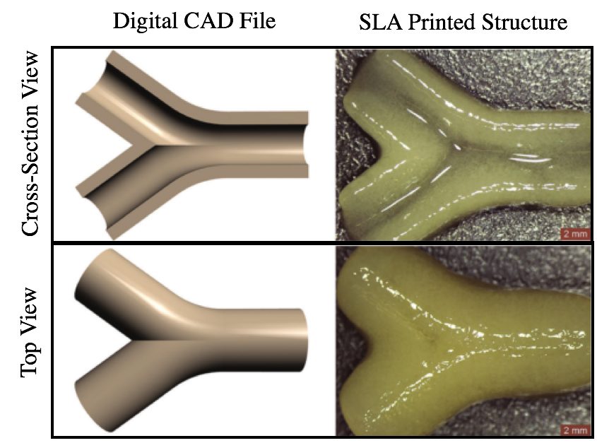
As is derived in chapter M, printing resolution in SLA is limited by the diffusion rate of radical initiating species that is particularly high in low viscosity hydrogel precursors consisting primarily of water. This has been addressed by adding an inert compound to the formulation that increases the viscosity, enabling ~1 mm feature size as shown in Figure 4. Unfortunately, there has been limited work to demonstrate true 3D structures with overhangs and internal channels with size less than ~2 mm. Chapter X demonstrates 3D printing of complex hydrogel structure including internal 250 micron channels via the use of a very high reactivity thiol-ene polymer that reduces the transport-limited resolution to as little as Y microns.
Figure 4 Work demonstrating SLA 3D printed hydrogel constructs with a channel, where the minimum feature size is ~1 mm, adapted from Elomaa et al.