Ankle-Foot Anatomy
The ankle-foot complex has two important functions in walking: stable the stance, and provide propulsion. Therefore, an understanding of the anatomy of this area is essential for designing lower extremity medical devices. The ankle joint is the articulation between the talus and the two bones (the distal tibia and the fibula) of the lower leg (seen in Figure 7). The ankle joint is a hinge joint allows flexion-extension movement as well as inversion-eversion (seen in Figure 8). The ankle allows approximately 25° dorsiflexion as well as 50° plantar flexion. For normal people, the inversion is about 5-10°, and the eversion is about 5°. The talus and the calcaneus provide inversion and eversion. During the passive motion, the articular surfaces and ligaments govern joint kinematics, with the articular surfaces sliding upon each other without appreciable tissue deformation

Ankle-Foot Anatomical Bone Structure

Figure 8 Movements of the foot at the ankle and tarsal joints: (a) dorsiflexion and plantar flexion; (b)
supination and pronation
The ankle joint is actuated by several muscle groups. The prime dorsiflexors of the foot are tibialis anterior, extensor digitorumlongus, while the major plantar flexors are gastrocnemius and the soleus.
Figure 9 Prime Dorsiflexors of the Ankle
Figure 10 the Major Plantar Flexors of the Ankle
The foot is usually described as an elastic arch structure consists of 26 bones with numerous articulations. Together, the foot provides the support of the body. During the walking, the metatarsophalangeal (MTP) joint provides propulsion (seen in Figure 11). The MTP joint allows approximately 70° dorsiflexion
Figure 11 Dorsiflexion of the metatarsophalangeal Joint
Human Gait
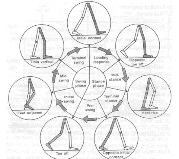
The human gait cycle includes two phases: the swing phase and the stance phase (seen in Figure 12). During the stance phase the foot is on the ground. The stance phase constitutes about 60% of the gait cycle and ends at the point of toe-off. The swing phase covers the remaining 40%. Drop foot is a gait abnormality which leads to inability to dorsiflex the foot during the swing phase. Nearly 20% of stroke survivors suffer from drop foot. Ankle-foot Orthoses (AFOs) are frequently prescribed to help stabilize the ankle-foot complex with limited dorsiflexion
Figure 12 Phases of Human Gait Cycle
Custom-made Ankle-Foot-Orthoses (AFOs)
The design of the AFO is essential as different designs are reported to affect outcomes in temporospatial parameters, ankle kinematics and knee kinematics. Parameters such as AFO ankle angle, AFO stiffness is based on clinical measurement. Some evidence indicates that the AFOs require individual adjustment so as to obtain optimal function. Currently, creating a custom-made orthosis is a time-consuming laborious work. The process showed in Figure 13 could take up to 4 hours by an experienced orthotist. The shape of the ankle-foot complex is captured by wrapping a shock and casting the leg. In this configuration key anatomical features are marked to help perform corrective modifications in a later fabrication process. The cast will be filled with plaster, and preheated thermoplastic is formed around the plaster. Once cool, the unwanted
plastic is cut away, and the remaining part is ground down and smoothed to a wearable AFO.
Figure 13 Traditional fabrication process of a customized AFO
Embraced with the rapid prototyping technique and 3D-scanning technique, several customized anklefoot orthoses have been rapid prototyped to demonstrate the feasibility of the computerized fabrication process.Northeastern University’s Biomedical Mechatronics Laboratory developed a patient specific AFO utilizing rapid prototyping technique (Seen in Figure 14). In this prototype, a kind of nylon-like Selective Laser Sintering (SLS) material is used to fabricate AFO. Conductive piezoresistive material was injected into the SLS AFO so as to capture stress and stiffness data
Figure 14 SLS AFO with C-SHIP Sensors
University of Delaware also developed a passive-dynamic AFO fabricated by fused deposition modeling (FDM) 3D printing technique. In addition, the strut thickness was tuned, and correlated to the experimental stiffness data to develop a virtual bending stiffness determination process.
Figure 15 Passive Dynamic AFOs
It is predicable that with the development of the advanced manufacturing process, orthotics will be further personalized to suit the patient.
Measurement of Lower Extremity Medical Devices
AFO stiffness plays an important role in determining the biomechanical function of AFO. Currently, AFO stiffness measurements could be divided into two main methods: bench testing and functional analysis. In the functional analysis, an AFO is embedded with sensors such as strain gauge, and is worn by subjects while walking. In the bench testing method, mechanical parameters are usually measured with an AFO attached to a measurement apparatus.The advantage of functional analysis is that the properties of the AFO could be combined with thelower-limb joint kinematics. However, parameters generated from human factors such as pathology will influence the results, which make it difficult to apply these results to improve the design of new AFOs. Conversely, experimental parameters are easy to control in bench analysis. Although the ISO structural test standard for an AFO has not been established, various measurement devices have been developed to analysis AFO performance. The UV University Medical Center has developed a measurement device named BRUCE to capture AFO several characteristics. Figure 16 indicates the schematic overview of the BRUCE. The design of the BRUCE is based on human leg anatomy which is driven manually. Besides, the BRUCE allows the MTP flexion-extension motion. The stiffness and the neutral angle around the ankle as well as MTP joint could be obtained by the device, and the results have been described as reliable and clinically applicable. However, since the actuation is driven manually, the device cannot be able
to perform dynamic measurement.
Figure 16 The Schematic Overview of BRUCE
Hong Kong Polytechnic University designed an automated device to measure the stiffness of articulated AFOs (seen in Figure 17). The device is actuated by a commercial hydraulic servo fatigue testing machine. A potentiometer is aligned with the rotary plate to capture ankle angle, while the force measurement is performed by a hand-held force gauge. The device has accuracy of 4% within repetitive 15° plantar flexion as well as 1% within dorsiflexion at the angular velocity of 10°/s. However, the device does not have automated mechanisms to measure stiffness. Also, the device might not be able to simulate the complexity of actual loading and individual biomechanical environments. Accurate measurements of orthotics are crucial and under-development in quantitative design of customized devices. The next generation bench testing systems for biomedical rehabilitation devices must be able to adjust to customized biomechanical anatomy parameters. The simulation of loadings should accurately reflect the actual human-device interface. Automated actuation and data acquisition is needed to simulate repeatable human motion, and obtained both static and dynamic mechanical characteristics. With the development of assessment systems for biomedical devices, quantitative prescription and fabrication of patient-specific rehabilitation devices will be practicable in industry in the future.
Figure 17 An Automatic Articular AFO Stiffness Measurement Device