TEG Optimum Output and Power Regulation
In this post, we talk about TEG Optimum Output and Power Regulation.
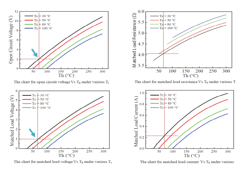
The electricity values from the commercial TEG are much lower than we expected. The main reason is the small temperature contrast between the hot and cold side of the device. The applied heat was too hot and transferred too quickly, but the heat sink was too small to dissipate the heat quickly. The experimental result is the initial verification of devices. The result should be improved in the future study. The maximum achievable power were found using analysis. the 5W – 5V TEG model’s specification that is related to the power generation for various cases.
The additional power from TEG can be added to the power source recharging regulator circuit. This approach can help to avoid the problems of losing connection between wireless microcontroller and Wi-Fi due to the low voltage supplied to the microcontroller. The original circuit uses 9V battery for the tracking devices and the TEG can add some supplementary power to the alternative power source when the original battery drops below the required voltage. However, we need to maintain the battery in the required voltage level to control the devices and communicate through the Wi-Fi enabled platform.
In fact, the wireless capable microcontroller is disabled to communicate wirelessly if the power source voltage drops below the minimum voltage for Wi-Fi connection in the specification although it operates at the low voltage as about 2.7 to 3.3V for the general signal generating function. Also, the motors cannot operate in full power if the voltage drops below the specified rating. If the batteries are switched to the rechargeable type and add the TEG output when the battery is charging , we can avoid the battery wasting problem and increase energy efficiency in the system.
