Rotary optical encoders
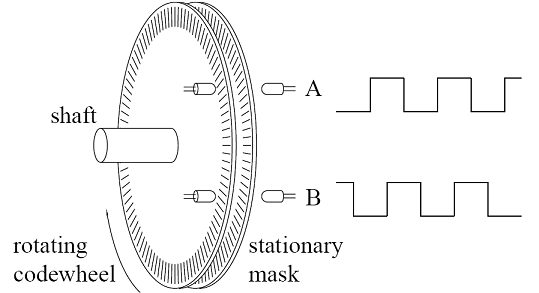
optical encoders Encoder is defined as an electromechanical device that measures motion or position. Encoders typically use optical sensors to generate electrical pulse train signals which are converted to position, motion, or direction . Figure 2.16 shows the main components of a rotary encoder including a disk, a light-emitting diode (LED), and a light detector. The disk is fixed on the rotating shaft for measuring the rotational motion. This disk has opaque and transparent sector patterns so that when the disk rotates, the opaque part stops the passage of the light to ray while the transparent part allows the light to ray to move through. This generates square-wave pulses that can be converted into motion or position. An encoder with just one set of pulses cannot be used to depict the direction of rotation. The use of two layers of code tracks that have sectors positioned 90 degrees out of phase from each other has shown in Figure 2.17. This will result in the two output channels A and B of the resulting quadrature encoder being used to show both position and direction of rotation.
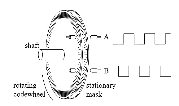
Figure 2.16 Rotary optical encoder main parts

Figure 2.17 Quadrature Encoder A and B Output Signals
Apart from these two channels (A and B), some of the quadrature encoders have a third output channel which sends out a single pulse per revolution; this pulse helps with the accurate determination of a reference position. This channel is called the zero or reference signal channel, in some encoders it is termed the index or the Z-Terminal. Another type of encoder apart from those mentioned earlier (the rotary or quadrature encoder) is the incremental encoder. This encoder is used to measure changes in position. As known in basic physics, it is possible to get velocity and acceleration from these changes in position measurements, but it is currently not possible to determine the absolute position of an object. This gives the need for another type of encoder called absolute encoder which can be used to determine the absolute position of an object. Differential encoder, another type of encoder, is to be used when encoders are to be used in electrically noisy environments. Differential encoder has two lines per each A and B signal. The two lines for the A signal are named A’ and A, and that of the B signal are B’ and B; the encoder works by taking differential measurements in order to preserve the integrity of the signal
Encoder measurement
A counter is used to make encoder measurements possible. The counter has a value which shows the number of edges low to high transitions in the waveform or pulse train counted. Counters majorly have three inputs named gate, source and up/down. The counter counts the waveform received at the source input, and according to the settings of the up/down line, it either increases or decreases the count. If the setting of the up/down line is “high” the counter increases the count, and if the setting is “low” the counter decreases the count. Figure 2.18 shows a basic model of the counter. Practically, most encoders have more than three terminals or pins that could be connected to external circuitry depending on how the encoder is to be used and also on the type of encoder, the cables of these terminals have different colors. One of these cables powers the encoder; another is called the 0V terminal. The other pins could be any/all of the A, B, and Z terminals described earlier. These terminals could also come in pairs for some encoders so as to enable the possibility of differential measurements.
Figure 2.18 Model of a counter
Figure 2.19 (a) below is a picture of the terminal cables of the Omron E6A2-CW3C encoder (the encoder used in this work) that has four terminal cables labeled as shown on the figure.Figure 2.19 (b) shows the terminal cables of an Automation Direct TRDNH10-RZVWD encoder. It has nine terminals, all labeled on the figure. This implies that there is a need to get familiar with the terminal cables of a particular encoder one aims to use and know when to use a particular terminal and where to connect each terminal. The encoder used in this work is the Omron E6A2-CW3C as mentioned earlier (shown in Figure 2.8 and 2.19(a)). The data acquisition device utilized is NI 6071E card and its required accessories. In the next section, the measurements obtained from the Omron E6A2-CW3C encoder using oscilloscope and also using the LabVIEW program without the noise reduction algorithm is presented. The proposed noise reduction LabVIEW program is then used to collect frequency readings and the differences between these sets of readings is discussed. Further analysis is run on the proposed noise reduction LabVIEW program.
Figure 2.19 (a) Omron E6A2-CW3C encoder (b) TRDNH10- RZVWD encoder
Throughout this section the encoder is run mounted on the generator’s shaft; a section of the generator set which also has the location of the encoder is shown in Figure 2.8.
Figure 2.8 Optical encoder mounted on the shaft