Monitoring the interplay of neuronal ensembles in the brain is important for understanding mechanisms underlying memory, learning and behavior. Recently a group of neuroscientists have proposed launching a large-scale, international public effort called “Brain Activity Map” (BAM) Project, aimed at reconstructing the full record of neural activity across complete neural circuits. They describe the neural circuit function as being emergent, meaning that it arises from complex interactions among millions of neurons and that the circuit state is not predictable from responses of individual sparsely sampled cells. They propose the dynamical mapping of the “functional connectome”, the patterns and sequences of neuronal firing by all neurons. Correlating this firing activity with both the connectivity of the circuit and its functional or behavioral output could enable the understanding of neuronal codes and the regulation of behavior and mental states. Some of the mental illnesses that could not be understood using single-level analysis, such as autism and schizophrenia, may be possible to explain on an emergent level analysis. Clearly, the benefits of getting the full dynamical picture of the brain will be invaluable to address many questions in neuroscience, but to achieve this vision there is a clear need to develop novel technologies and significant innovations in systems engineering.
At present, population coding is studied either by monitoring the spiking activity of a few hundreds of individual neurons working with intact, living animals or by studying the basics of distributed information processing using cultured neuronal networks. Cultured neuronal networks lack many features of real brain, but they retain others such as developing synaptic connections and exhibiting different patterns of electrical activity. The neural activity cannot be correlated to a behavioral or mental output as in vivo, but it can be correlated to a structural connectome and to stimulation patterns. Advancement in micro-electrode array technology and multi-photon microscopy, has made it possible that every cell in a cultured monolayer network of dissociated neurons can be observed, monitored, stimulated and manipulated with temporal resolution in the sub-millisecond range, and spatial resolution in the submicron range, in a non-destructive manner. Currently, such detailed analysis is not feasible in living animals, or even brain slices, but it remains an open question however, whether any of the processing done by cultured neurons is relevant to that carried out by intact brain.
This chapter serves to present efforts from a number of research groups to upgrade the recording capabilities of neuronal activity to higher spatial and temporal resolution across a large-scale neuronal ensemble to approach the model of in vivo brain. It will review some of these efforts reported on the data acquisition level. With the increasing number of recording sites, the chapter also discusses architecture design considerations at the spike detection level.
2.1. Multi-electrode Arrays:
Multielectrode arrays or microelectrode arrays are data acquisition devices that contain multiple plates or shanks through which neural signals are acquired, basically serving as neural interfaces that connect neurons to electronic circuitry. The signal then passes through amplification and filtering to remove some of the background noise. MEAs can be classified into two groups: implantable MEAs, used in vivo, and non-implantable MEAs, used in vitro. Using advances in multisite microelectrode array fabrication techniques varying shape and recording capacity of the electrodes, it is possible to record the activity of tens to hundreds of neurons in parallel. Integrated microelectronic circuits were applied to enable the transition to even higher recording capacities. Development of in vivo and in vitro multi-electrode probes share many of the same hardware and data analysis problems and mutually contribute to the advancement of the state of the art.
2.1.1 In Vitro Micro-Electrode Arrays:
Multi-electrode array culture dishes allow simultaneous recoding from and stimulation of neurons. These wired Petri dishes are also called planar electrode arrays. Early microelectrode developments by Gross, Wise, Meister and others paved the way for enabling chronic multi-single-cell recording. They were able to record neural spike potentials with good fidelity from a few tens of neurons.
MEA’s have become commercially available just within the last decade. MEA systems capable of recording at least 60 electrodes are produced by MultiChannel Systems of Germany, and Panasonic of Japan. Guenter Gross supplies MEAs that can be used with multi-electrode processing hardware and software made by Plexon Inc. MEAs typically consist of less than 100 planar metal electrodes on an insulating glass substrate with a diameter > 30μm and a pitch >100μm. For commercially available MEAs, amplification and filtering are realized by discrete off-chip components.
Considering the dimensions of neurons, which range from below 10μm for vertebrates up to 100μm for invertebrates, the development of high-density arrays was needed to acquire more details from cell-based biological experiments on brain slices and to elucidate the contribution of individual cells to collective network. An advanced multi-electrode array system has been developed to study how the retina processes and encodes visual images. This system can simultaneously record the extracellular electrical activity from hundreds of retinal output neurons and consists of 512 planar microelectrodes with a sensitive area of 1.7 mm² and a noise level of a few μV. However, some brain structures, such as hippocampus or cerebral cortex, extend over distances of many millimeters. To record from these larger structures, an increased density of electrodes and a larger array would be required in order to fully analyze all the neurons of interest.
CMOS-based devices presents several advantages for managing a large number of electrode channels’ interconnections, multiplexing, amplification and filtering. They have been initially implemented for in vivo neural probe recordings. Later they have been used for in vitro devices at a larger scale to overcome the connectivity limitation by making use of on-chip signal multiplexing. A number of voltage recording microelectrode array devices have been developed with significantly higher electrode densities and larger areas. Due to hardware bandwidth limitations, these devices all make some compromise between speed, electrode count, multiplexed sampling, and noise.
A high-density 128×128 biosensor array CMOS chip was designed featuring a frame rate of 2K frames per second, and a pitch of 7.8μmx7.8μm over 1mm² extent. The device has a very high spatial resolution recording of small areas of tissue, but was reported to have noise levels in the range of 250μVrms, which could make recording smaller extracellular spike signals (20-100μV) a challenge. The simultaneous recording from all electrodes required the front-end amplifiers being placed in each recording site, which, due to area constraints, entailed the high noise levels.
A switch-matrix-based high-density microelectrode array was developed as a hybrid between low electrode count and high resolution arrays. The device has only 126 output channels but these could be digitally selected from among 11,000 electrodes, separated by a pitch of 18μm, using a reconfigurable electrode/readout-channel routing. The device has very low noise levels of 7-9μV, since the front-end circuitry were placed outside the array, where sufficient area for low-noise circuit implementation is available.
Imfeld and coworkers developed an electrode multiplexing , 4096 pixel recording array with a 42 μm pitch and a 2.7mmx2.7mm extent that can record the full frame at a rate of 8KHz. The device has high spatial resolution, a relatively good temporal resolution and a wide extent of ~7mm². The data recording has a hardware implementation inspired by image/video processing concepts. It implements an Active Pixel Sensor (APS) concept CMOS design, acquiring the data as a time sequence of images. Basic amplification was performed underneath each electrode, and a tradeoff between spatial resolution and noise dictated the inter-electrode spacing. The noise level is in the range of ~26μV rms. The complete architecture of the acquisition system is shown in Fig. 2.1. Control and timing of the APS-MEA as well as the bank of the Analog to Digital Converters (ADC) is performed by an FPGA. Filtering the 4096 channels in real time is also carried out on the same FPGA.
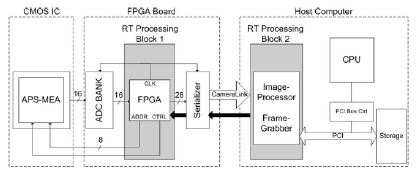
Fig 2.1 Block diagram of the acquisition platform.
Recently a high-electrode count Pico-current Imaging Array (PIA), based on an 81,920 pixel readout integrated circuit camera chip was developed. While originally designed for interfacing to infrared photo-detector arrays, it was adapted for neuron recording by bonding it to microwire glass. The full frame of an area of 9.6mm by 7.7mm can be recorded at 100Hz.
2.1.2 In Vivo Micro-Electrode Arrays:
Implantable MEA research considers more requirements and restrictions for acute and chronic implantation. Some research areas focus on the fabrication process, insertion techniques, chronic response of tissue on the implant, wireless implant design and power issues. In this section the main focus will be only on presenting a few of the research efforts on increasing the number of recording sites of neural signals. Some Labs are mainly interested in monitoring more neurons in different cortical areas of the brain, while others are interested in changing the microstructure of the neural probes to increase the spatial resolution.
Researchers at the Duke University lab published a paradigm for recording the activity of single cortical neurons from awake, behaving monkeys. They implanted high-density microwire arrays, developed at Duke University, totaling up to 704 microwires per subject in five cortical areas. Early this year the lab announced that they were able to simultaneously record the firing patterns of close to 2000 neurons. Four multielectrode arrays with 448 electrodes were inserted in rhesus monkey motor and sensory cortices of both hemispheres. There are no publications yet explaining the detailed instrumentation used.
The microwire and similarly structured silicon-based arrays feature one recording site per wire, which limits the capability of the array to capture dense neuronal activity in 3-dimensional setting. Alternatively in 1985 the planar microelectrode array was introduced, using multiple electrodes arranged on implantable silicon shafts. The planar microelectrodes increased the recording spatial precision. It was later modified by proposing double-sided electrodes. These devices contain electrodes on two parallel planes separated by the thickness of the implantable shaft, presenting a building block for a 3-dimensional recording geometry.
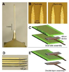
Du and coworkers at the California Institute of Technology have fabricated a dual-side electrode array by patterning recording sites at the front and back of an implantable microstructure. They proposed stacking several two-dimensional multishank arrays into three dimensional probe arrays, to access 3-D neuronal structures as shown in Fig. 2.2.
The nano-probe design presents a potential for hundreds or thousands of recording sites, but it holds a high risk of brain tissue damage. To minimize the disruptive interface between the silicon electrodes and the brain, the nano-probes will pass through more testing and evaluation to determine the optimal shaft size and shaft spacing.
It is evident that there are several efforts aiming to increase the number of recording channels in vivo as well as in vitro and in situ, which leads us to the next section of presenting the available signal processing tools and their capability of handling the resulting high amount of recorded data.

Fig. 2.2. Dual-side and double-layer microelectrode arrays were built on thin silicon shafts. A: front view of the device. The shaft dimensions are 4 mm x70 μm x50 μm (l x w x t). B: expanded view of the front and back sides of the dual-side array. The recording sites have a geometric area of 100μm². C: layers involved in connecting dual-side arrays to flexible printed circuit boards (PCBs, green), one board for each side. Electrical connections were made via low-profile flip-chip bonds. D: view of the tip of a 2 x 2 shaft, double-layer array. E: a modular assembly scheme used to make the multilayer structure. Note that the PCB contained conducting leads on both sides and thus the same board connected to the upper recording sites on the bottom layer and the lower sites on the top layer.
2.2. Neural Signal Processing Systems:
Recordings of extracellular neural activity are used in many research studies and clinical applications. Usually, these signals are analyzed as a point process, and spike detection is used to estimate the times at which action potentials from one or more neurons occurred. Recordings from high-density MEAs and low-impedance microelectrodes often have a low signal-to-noise ratio (SNR < 10) and contain action potentials from more than one neuron. Hence, spike detection is often followed by spike sorting, that involves clustering, to assign each event to separate neurons based on AP waveforms.
2.2.1 Spike Detection Algorithms:
The main challenge in detecting spikes is the interference due to background noise. Various spike detection algorithms with different levels of complexity and performance have been presented. The absolute threshold method is widely used as it requires the least computations, but it is highly sensitive to background noise. Various techniques have been proposed for autonomously selecting the threshold based on the statistical characteristics of the recorded signal, while others set the threshold based on a visual inspection of the detected spikes. A different type of algorithms is based on template matching. These algorithms scan the recorded signal for instances, where segments of the signal are similar to templates of spike waveforms. In this case a priori knowledge of the spike waveforms is required and the user should supply a threshold for similarity measures. A different approach suggests using a preprocessors, such as the Nonlinear Energy Operator NEO to give emphasis to the spikes relative to the noise before applying the absolute threshold, consequently improving the spike detection performance.
2.2.2 Overview on Existing Neural Signal Processing Systems:
Existing commercial recording systems are limited to a few hundred channels and rely on multiple sequential logic processors connected in parallel. While functional, such systems are difficult to manage, and do not scale well to larger channel counts. The paradigm described by researchers at Duke University for acquiring neural signals from monkeys incorporated the multichannel acquisition processor MAP by Plexon. The MAP recorded all the events that crossed the voltage threshold, set by the user, for subsequent offline spike sorting analysis. Each MAP processor can handle up to 128 channels. For their experiments, they used a custom made MAP cluster, formed by three 128-channel MAPs connected in parallel and synchronized by a common 2MHz clock signal. The initial step in all recording sessions required the experimenter to manually set the voltage threshold for each of the MAP channels connected to an implanted microwire. The threshold was set based on visual inspection of the original analog signals displayed in an oscilloscope as well as the digital signal displayed on the screen of the computer controlling the MAP. With the increasing number of recording channels, it becomes impractical to require the user to tune the spike detection algorithm to the signal properties visualized on each channel. Currently, Plexon is offering an upgraded version of the MAP called OmniPlex® D Neural Data Acquisition System. The system can handle up to 256 channels sampled at 40KHz with a sample precision of 16 bits.
With the rising demand to process a large number of similarly structured parallel channels in real time, there has been an emerging interest in hardware implementation over sequential processors. FPGAs offer massive parallel processing performance and reconfigurable flexibility, which makes them an attractive alternative for real-time signal processing.
The data acquisition systems integrated with the high-density MEAs presented in section 2.1. perform signal conditioning in terms of amplification and filtering, and then send the complete signal to a host PC for storage, off-line spike detection and clustering. As high-density MEA platform produce data streams in the range of hundreds or thousands of Megabits, the amount of data storage required increases drastically with longer recording times. Real-time spike detection and data compression become vital to limit the amount of data storage.
2.3. Spike-Based Data Reduction:
The idea of data reduction has been addressed mainly in wireless implantable devices for Brain-Machine-Interfaces. Several efforts have been proposed to implement on-line hardware spike detection and send only the spike waveforms while disregarding the interspike samples. The spike waveforms are the only information needed for successive spike sorting. With a limited telemetry bandwidth, it was essential to consider spike-based data compression algorithms to reduce the amount of sent data. With power restrictions of implantable devices, there was also a need to avoid high power consumption associated with the continuous transmission of raw data. The proposed schemes aimed at providing an efficient use of the available transmission bandwidth and an increase of the device throughput. Based on the sparse nature of the neural signal with respect to time, and the average neuron firing rates, the amount of sent data can be reduced to approximately ~2.25% of the total amount of raw data.
With a focus on telemetry transmission, Bossetti et al raised an important design consideration for spike-based data reduction in real-time. They demonstrated that although the spike-based compression might be very appealing from the point of view of average bandwidth, it is subject to telemetry bottlenecks during periods of multichannel neuron bursting causing queuing-based transmission delays at the output buffer. They drew the attention to the relation between the ratio of the output to average input bandwidth and transmission latency, the number of samples per spike waveform, the mean firing rate MFR, and the needed queue depth of the output buffer memory. Bottlenecks and latencies are mainly a consequence of accumulating the input data samples over short periods of time before their transmission at the output, waiting for the AP waveform to complete at the output queue. The research paper has concentrated mainly on the transmission delay. The hardware implementation delay is the time between the arrival of the spike waveform at the input buffer and its appearance on the output buffer. The method of spike detection employed will dictate the size and temporal pattern of spike data arriving at the output buffer. These patterns could impact the timing significantly. Aside from the delay depending on the scheme control and data handling between the input and output buffers, there are other delays related to the computational overhead and memory read/write times, that depend on the system clock. The performance of the spike detector will also affect the required output bandwidth. A high false detection rate will increase the overall MFR and change the system design.
2.4. Spike Detector Design Schemes:
The design of the data flow in the spike detection hardware-implementation defines the system latency and memory requirements. With the increasing demand to monitor thousands of recording channels, the efficient use of hardware resources, especially memory blocks on the FPGA becomes vital. Only a few literature have presented detailed patterns and sequences of the data flow on their spike-based compression architectures. This section presents two examples of spike detection architectures with different data flow sequences, and discusses their possible application on high channel-counts. The first example is a spike detection scheme designed for an implantable data acquisition system for BMI application. The second example is an architecture of a Neural Spike Detection platform NSP.
2.4.1. Spike Detection Architecture for Implantable Application:
A spike-detection based data reduction scheme described in literature handles the time division multiplexed data recorded from 16 channels. In this design the 64 most recent samples from each channel are stored in the input data storage buffer memory. Once a spike has been detected on a channel, the hardware waits until an additional set of 34 samples, representing the spike waveform refractory period, from the same channel has been acquired. After the 45 samples of the AP waveform are completed in the input buffer memory, the spike waveform waits for its turn in a queue for detected spikes to be written out to the FIFO buffer, where it is held until the embedded PC and wireless card transmit them to the host station.
The scheme worked fine with 16 channels, but if the design is used for higher channel counts then some modifications must be considered. For example, if the spike detection unit handles many channels in a time division multiplexed approach, then the system must extend the memory space assigned for each channel to ensure that the detected spike waveform samples are copied from the input buffer to the output FIFO before they are overwritten by new samples. Another solution would be increasing the clock ratio between the reading and writing clock rates of the input buffer. As the copying process from the input buffers is queuing based, the more channels sharing the same queue, the slower would be the route. To avoid high memory usage on the hardware, when increasing the number of recording channels handled, a different design sequence might be considered. For example, copying the AP waveform in single samples, as they arrive at the input buffer, or in small groups of samples to the output buffer, in order to decrease the memory space assigned for each channel in the input buffer.
Another implementation approach might be to replicate the 16-channel spike detection unit and use an intermediate FIFO for each unit to store the spikes before sending them to the common output FIFO. This latter transmission may be controlled by a queuing-based scheme. In this case the queuing based delay must be monitored closely as the AP waveforms will passes through queuing-based transmission three times. Once to be copied from the input buffer to the intermediate unit FIFO, then from the intermediate FIFO to an output FIFO common to all spike detection units and finally queued in the output FIFO for transmission to the host. The delay is expected to increase in case of neuron bursting across the channels.