
Power Agent Model
In this post, we talk about Power Agent Model.
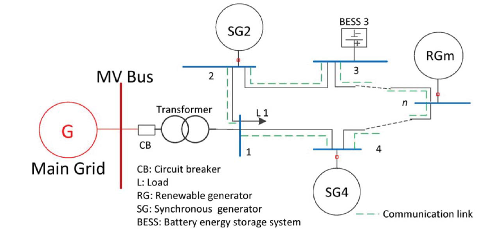
The nodes in the standard multi-bus systems have been previously represented by the power agents. They are specified as producer and consumer agents . Since the the above focused on the properties of the topology, the power agents were designed to be stationary. Therefore, generator (producer) agents can supply the load (consumer) agents discontinuously from iteration to iteration. Their status cannot change based upon the status of the neighboring load agents. Thus the control process cannot happen in continuous-time. This is considered the main issue from the previous proposed centralized approach. When considering the real-time control algorithm and its applicability on physical power systems, we need to improve the design of the agents. In order to make reactive changes upon the status of power flow, a novel power agent model is proposed. It is derived from Automatic Generation Controller (AGV) from the real-time power system. This agent model can be universally applied to all the components in power distribution systems, even for smart grid components like RGs, ESSs, SGs as well as loads.
supplementary controller is the core module of this power agent model. It has the Agent Control Error (ACE) as the input, which is the sum of the feedback
frequency deviation multiplied by a frequency-bias factor B, and the power flow deviation
from the neighboring agents. The ACE can be formulated as:

Therefore, each power agent that participates in the power distribution system has a
supplementary controller that receives the ACE as the input. The controller outputs regulation feedbacks and leads the reactions of the generator and load. Depending on the output, either the generator turbine will change its steam valve position or the load change the power it consumes. Specifically, the module 1R in the figure causes the reaction. It is a regulator with R as the Speed Regulation, which has a positive value:
where both R and f are percentage values. This means the slope of the load-frequency
control characteristic is (−R). For example, regulation R equal to 3% implies that a 0.1 per unit change in the electrical neighbor loads corresponds to 0.3% change in the base frequency. Thus, the output of this model, connected to the turbine, which performs the steam valve adjustment at the turbine. The output voltage
of the generator agent will be changed accordingly. The supplementary controller here in the model can be any Proportional-Integral-Derivative (PID) controller widely used in industrial control systems. In this dissertation, we pick the simplest gain controller Ks as the supplementary controller.
In order to make this supplementary controller act in continuous-time, and be universal to all the components in power distribution systems, a definition of agent dynamic should be given as:
Then the power flow deviation in supplementary controller can be defined from the above definition:
where the x(i) – x(j) is the state error between agents and in the dynamics of agents in the next section.