Potential Impacts of PV Integration on Distribution Networks
Distribution Networks
The conventional power grid is designed to accommodate a unidirectional ow of electric power from central generation units to transmission lines that will deliver the power to distribution feeders and consequently to the loads . With the introduction of DG, specically PV systems, the ow of electric power becomes bidirectional. The existing distribution system components (such
as voltage regulators, protection devices and other switch gears) were not designed to handle bidirectional power flow. Therefore, the potential impacts that accompany the integration of power electronic-based PV systems are of great concern for power utilities. The severity of the potential impacts caused by the integration of PV systems in distribution networks is in uenced by various parameters such as the location of the PV system, the stiffness of the distribution network, the voltage regulation equipment present in the feeder, the size of the PV plant, and the proximity of the PV system to other inverter-based generation sources. Moreover, the variability of solar irradiance, predictability of the operation of the PV system under different
conditions, and the dispatchability of the PV plant in the presence of energy storage also have a great effect on the potential impacts of the PV systems.
General Potential Impacts
General system level impacts affect the operation of the distribution system. Some of these impacts are:
1. Resonance caused by the interaction between the output capacitance of multiple PV inverters and the network impedance.
2. Tripping of multiple PV systems which could be attributed to different reasons and may lead to system overloading and possibly line outages causing system stability risks.
3. Reverse power ow which may cause relay malfunctioning and raises system protection con- cerns .
4. Circuit reclosing coordination when a PV plant is disconnected and is brought back online.
5. DC injection, ferro-resonance, equipment overloading due to loss of load while the PV system is still in operation, etc.
Equipment Specic Impacts. These are the effects that the different system impacts will have on the system equipment. Below are some of the equipment that can be affected by the PV system integration:
1. Distribution transformers: the high penetration of PV systems may affect the transformer insulation life due the variability of generation and phase unbalances that can be introduced at the distribution level .
2. Protection equipment (relays, switches, reclosers, fuses): the high PV system penetration may affect the protection coordination schemes and cause false and frequent tripping of various protection equipment .
3. Communication equipment: data acquisition equipment, smart meters, phasor measurement units (PMU), data transmitters and receivers may also be affected by sudden surges caused by nearby DG.
4. Voltage regulation devices: Switched capacitor bank (SCB), switched voltage regulators (SVR), on-load tap changer (OLTC) transformers may be prone to premature wear and tear due to the frequent operation caused by the uctuation in voltage levels resulting from the variable PV output.
Technical Potential Impacts
Power quality-related phenomena have become more visible as power electronic-based DG integration increases on the distribution side of the network. IEEE 1159-2009 standard and IEC 61000-4-7 standard both deal with power quality and elec- tromagnetic phenomena. Power quality electromagnetic phenomena are categorized based on their time duration into:
1. Transients: high frequency impulsive and oscillatory phenomena ranging from a few nanosec- onds to few milliseconds.
2. Short duration root mean square (RMS) variations: such as sag (decrease) or swell (increase) in the voltage waveform lasting for a few seconds.
3. Long duration RMS variations: such as sustained signal interruption lasting more than a minute.
4. Imbalance in voltage and current signals.
5. Waveform distortions in which a signal is distorted by undesired frequencies (DC offset, harmonics, inter-harmonics, notching, noise).
6. Voltage uctuations and power frequency variations.
These phenomena are traditionally caused by large machines, welding equipment, furnace tools, and different other industrial scale loads; however, they are limited and controllable due to the predictability of the operation of these devices. On the other hand, power quality issues caused by PV systems are uncontrollable and unpredictable due to the nature of the solar energy resource. Harmonic Distortions are power quality distortions in the power system’s sinusoidal wave fre- quency introduced by frequencies that are multiples of the fundamental frequency. Harmonics are introduced into the system through non-linear equipment such as static power converters, arc dis- charge devices, saturated magnetic devices, and rotating machines . These non-linear devices can alter the sinusoidal nature of the alternating current (AC) resulting in harmonic current ow. In the case of PV systems, harmonics are introduced by the switching of the power electronic inverters. The switching of PV inverters is achieved through pulse width modulation (PWM) tech- niques. All PWM methods inherently generate harmonics and noise originating from the high dv and di dt semiconductor switching transients . Inverters with higher harmonics can degrade the current harmonic distortion levels between 7%_16% . Small-scale rooftop PV systems typ- ically use single-phase inverters that usually have no signicant impact on the systems . A study in Denmark showed that the current harmonic contribution of small-scale PV installations in a neighborhood was less that 0:65% and there was no detected difference in measuring voltage distortion of phases with and without PV . A different study showed very little connection between the number of PV installations and the current harmonic distortion. Moreover, the rate of harmonic current increase was found to be not necessarily proportional to the increase in the number of connected units . In addition, a study that was done in a village in Australia showed that the voltage harmonics were 1:9%, which is far below the IEEE-519 limits (5%) even when all PV inverters where operating at the same time . All these studies suggest that the impacts of small-scale PV inverters on harmonic distortion are negligible. Even leading standards on PV integration such as IEEE-1547, UL-1741, and FCC-15B all guarantee that inverters do not generate excessive noise and harmonics which can contaminate the AC grid . However, the studies presented above do not rule out the harmonic impacts of PV systems. For instance, in small distributed (decentralized) PV systems, the PV inverters can generate highly distorted current waveform so that the cumulative effect of them in a high PV penetration scenario can create hot spots within nearby transformers thus causing eddy currents, copper losses, and overheating of the transformer . Moreover, in case of large-scale PV systems connected to low voltage networks on the distribution side, the total harmonic distortion (THD) level could increase higher than 5% . Furthermore, the THD level increases to a dangerous limit as non-linear loads are added to the system . Voltage Fluctuation and Flicker are also power quality phenomena that are suspected to appear in distribution networks with high PV penetration. Voltage uctuations are generally considered to be cyclic variations in the voltage where the change in the amplitude does not exceed 10% of the nominal voltage . Flicker is a form of voltage uctuations that gives rise to noticeable illumination changes from the lighting equipment which can be irritating for the human perception. Repeated rapid changes in PV output due to fast changes in solar irradiance caused by moving clouds can cause voltage uctuations . The severity of icker caused by PV systems and its eects on the network depend primarily on the stiffness of the location where the PV system is connected. The farther the PV system is from the substation, the uctuations will be more severe. These voltage disturbances will affect the vulnerable loads in the system. Minicomputers, electronic cash registers, and data terminals are few examples of the susceptible loads that are often impacted by voltage disturbances . These uctuations could also impact voltage regulators (OLTC, SCB, SVR) and protection devices .
Unintentional Islanding
Unintentional Islanding
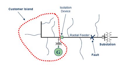
Unintentional islanding is a major concern in electric grids with interconnected PV systems due to the potential impacts on the system operation, equipment, and loads. Islanding occurs when a section of the feeder is isolated from the source (substation) and the loads in that section continue to be supported by the DG sources (PV systems) connected to it. For example, if protection devices are designed to automatically reconnect after a fault, there’s a risk that the current and voltage in the islanded section and the rest of the grid will be out of phase which could damage the PV system, grid equipment, and loads . Moreover, islanding poses some risks on the workers trying to restore power after a certain event while some parts of the network remain energized . Energized conductors due to a nearby PV system may also cause some public safety hazards . In addition, the utility cannot control the quality of power delivered to the islanded customers. The island may also cause loss of coordination between protection devices due to the change in the short circuit current . The detection and protection against the hazards of islanding is known as anti-islanding protection. Anti-islanding detection is mandatory for systems with interconnected PV systems . Islanding detection could be implemented through the PV inverter controls or through other utility monitoring and system level controls. Inverter-based islanding detection techniques are categorized into passive methods and active methods. Passive methods are based on monitoring certain power system parameters (amplitude, fre- quency, phase, or voltage harmonics) until a change is detected which is caused by the power mismatch after the disconnection. Passive methods do not disturb the normal operation of the system since they rely mainly on monitoring. The disadvantage of passive methods is the pres- ence of non-detection zones (NDZ). NDZ is a system operation zone in which the anti-islanding passive method might fail to detect the island, thus raising concerns regarding the reliability of passive detection methods. Some of the passive detection methods include: Over/Under Frequency – Over/Under Voltage (OUF-OUV) method, Phase Jump Detection, and Harmonic Detection . Active methods are more complex than passive methods because they require more than just monitoring the system. Active methods rely on the generation of a small perturbation that will eventually generate small change in frequency, phase, harmonics, active power or reactive power. If the grid is still connected, small perturbations will not have measurable impacts on the system. If a small perturbation is able to affect the system it means that an island situation is detected. Some of the active detection methods include: Frequency Drift Methods (Active Frequency Drift, Slip-model Frequency Shift, SANDIA Frequency Shift, GE Frequency Shift, etc.), Voltage Drift Methods, and Grid Impedance Estimation .
