A Hybrid car with navigation and safety and propulsion system run 2 million lines of embedded code.
MATLAB and Simulink help model based designer to design model with benefits such as faster design, higher quality, lower cost and greater flexibility.
Simulink is a popular tool in MATLAB software, which used for many industries such as Automotive, Aerospace, Defense.
NASA used MATLAB and Simulink for Mars’s exploration program.
ALSTOM used Simulink for high-speed rail.
Model-based design begins with a system model where you capture idea and requirements. The model is executable specification that let your team collaborate across roles and modeling domain. You can simulate the model or perform and rapid prototyping on it to explore design trade-offs.
With iteration, you refine the system model to optimize your design.
When your design is ready for implementation, You can generate code automatically. so, eliminates hand-coding errors. Finally, You verify your implementation through costimulation. process in loop and hardware in loop testing.
The model-based design gives you the freedom to innovate, by making it easy to try new ideas and explore design problems easily.
Automatic steps such as code generation speeding up the overall development process.
By moving the design task from the lab and field to the desktop, Model-Based Design is transforming the way engineers and scientists work. And it’s advanced engineering research and universities at thousands of universities worldwide.
https://www.mathworks.com/solutions/model-based-design.html
Why we use MATLAB/Simulink for rapid prototyping
The attracting features of using MATLAB/Simulink for BeagleBoard software development are the automatic code generation and the performance optimization by tuning parameters on the fly. This is a fast and inexpensive way for hobbyists and engineers to verify and evaluate their designs early, so that design defects can be found and fixed early.
You can design your data processing algorithms in a user-friendly graphical modular environment and then, in a few minutes time and without intensive manual coding, you see your algorithms running as standalone applications on the BeagleBoard.
This is particularly useful when your application involves complicated audio/video processing and needs many trial-and-error iterations for performance optimization.
The advantages of rapid prototyping by MATLAB/Simulink are as follows:
• Focus on innovation and data processing algorithm design.
• Allows you to work in design, coding, deployment, and testing and move quickly between each process.
• Simulink models and data processing algorithms can be auto-coded to C, compiled, and deployed as standalone applications at BeagleBoard.
• Graphical modular programming and automatic code generation make embedded software development easier.
• Obvious advantages for a small research project and student DIYs in terms of shorter development time and easier learning curves.
• Intensive simulation to enable “right-first-time” design.
And most importantly, the BeagleBoard support from MATLAB/Simulink now has wide availability and easy access for free. Since MATLAB 2012a, Simulink has a built-in support for BeagleBoard. This BeagleBoard support is also available in MATLAB and Simulink Student Version. You may also ask MathWorks for a trial version (https://www.mathworks.co.uk/products/matlab/trial.html) which also includes the built-in BeagleBoard support.
Model-Based Design Workflow
Rather than relying on physical prototypes and textual specifications, Model-Based Design uses a system model as an executable specification throughout development. It supports system- and component-level design and simulation, automatic code generation, and continuous test and verification.
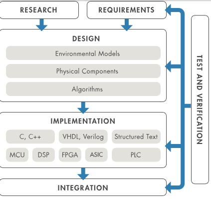
DESIGN AND SIMULATION
The model includes every component that affects system behavior – algorithms; control logic; physical components; and IP developed in MATLAB, C, HDL, or domain-specific modeling tools. Simulation lets you analyze system performance in conditions otherwise too expensive, risky, or time-consuming to consider.
Traditional Design Process
You can see the disadvantages of each step in the traditional design process.
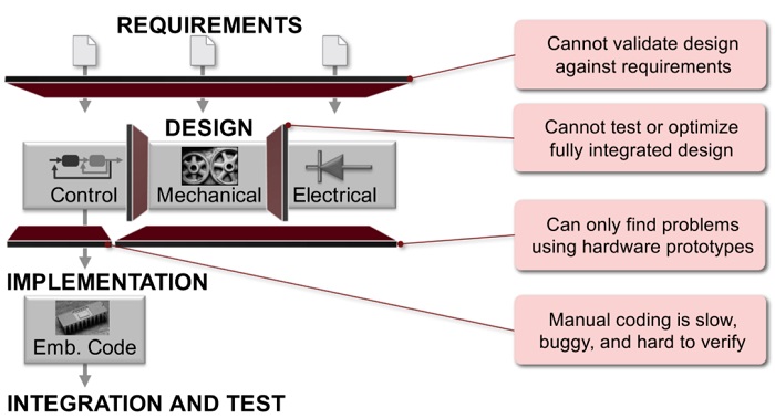
At the requirements step, We define the requirements for our design, so we can not validate design against requirements.
Then, We make the model in Simulink with electrical engineering blocks or mechanical engineering blocks or control engineering blocks. In the design step, We cannot test or optimize a fully integrated design. We can not use mechanical and electrical and power system blocks with each other.
Then, We have implementation step that we implement our model on hardware. In this method, We can not find problems using hardware prototypes and manual coding is used that has some disadvantages such as slow speed, buggy code and hard to verify.
Model-Based Design for embedded software development lowers costs by identifying defects early in the development process and reducing the total number of latent defects. By helping companies deliver higher quality systems at lower cost and in less time, Model-Based Design provides a competitive advantage.

Requirements are the same in the last approach and written in Microsoft Word or other type software.
The requirements are used to develop an executable specification in the form of models. These model can be written in a paper before developing in form of models in Simulink.
Engineers use these models to clarify requirements and specifications. The models are then elaborated to develop a detailed design. Using the tools for Model-Based Design, engineers can simulate the design at the system level, uncovering interface defects before implementation. Once the design is finalized, the engineers automatically generate production code and test cases from the models.
This workflow enables engineers to stay in the same environment from the requirement to test, minimizing the amount of manual work. In addition, testing can begin at the requirement phase when engineers simulate their executable specifications in models to verify that the requirements are met. As a result, defects are caught and removed earlier, lowering the total cost of development.
Generally speaking, there are four steps involved in the model-based design by Simulink:
- Building executable specification with models
- Performing design with Simulation
- Achieving implementation with the automatic code generator using Real-time Workshop Embedded Coder
- Test & Verification
Code generation
When generating C code from the Simulink model control, seven different files are generated. Control.c contains entry points for code implementing the model algorithm. It includes an initialization function, a step function and a terminate function that are called in the main file. The ert_main.c file that is generated is not used. Instead, the step function is called from the Cyclic.c file used in the PLC implementation. Control.h declares model data structure and a public interface to the model entry points and data structures. control_types.h is a macro guard, which is used to avoid the problem of double inclusion. That occurs when having one or more data type definitions to a generated header file, making sure that there will be no identifier clashes. Control_private.h contains local macros and local data that are required by the model and subsystems. The rtwtypes.h defines data types, structures and macro guards required by the generated code.
Student version supports Raspberry Pi, Arduino, LEGO, BeagleBoard, PandaBoard, Gumstix, …
To check the connection of a board to MATLAB, use ping command :
!ping ip.add.re.ss
After installing package hardware for a special hardware, You can use the block in this library for reading inputs ways (video, audio) in Simulink.
Video Capture block reads video from the board and produces R, G, B data. We can implement any image processing algorithms in here. There is a very interesting note in here any type of MATLAB command can be converted to code that can be run by final hardware.
Solver of Simulink is selected as FixedStepDiscrete. It means we can not use Continuous time simulation.
MATLAB is about using the OPC Toolbox for real-time communication between PLC and MATLAB which is a reliable and secure communication.
RSLinx have capabilities to support OPC connectivity to maximize the interoperability between clients and servers. It’s an OPC compliant server that enables data interchange between HMIs and other OPC Clients and Allen Bradley PLCs. This feature enables us to provide communication between PLC and MATLAB [5].
Simulink PLC Coder generates hardware-independent IEC 61131 structured text from Simulink models, Stateflow charts, and Embedded MATLAB functions. The structured text is generated in PLCOpen XML and other file formats supported by widely used integrated development environments (IDEs). As a result, you can compile and deploy your application to numerous programmable logic controller (PLC) and programmable automation controller (PAC) devices.
Simulink PLC Coder™ generates hardware-independent IEC 61131-3 Structured Text and Ladder Diagrams from Simulink® models, Stateflow® charts, and MATLAB® functions. The Structured Text and Ladder Diagrams are generated in PLCopen XML and other file formats supported by widely used integrated development environments (IDEs) including 3S-Smart Software Solutions CODESYS, Rockwell Automation Studio 5000, Siemens TIA Portal, and Omron Sysmac Studio. As a result, you can compile and deploy your application to numerous programmable logic controller (PLC) and programmable automation controller (PAC) devices.
Are they interested in generating the PLC program from a Simulink model? If so, then use PLC Coder for IEC 61131-3 Structured Text code generation.
ISO 26262
ISO 26262 (Road vehicles — Functional safety) is an international functional safety standard. It is an adaptation of IEC 61508 specific to the application sector of electrical and electronic systems in the road vehicle industry. It consists of 10 parts: ISO 26262-1 to ISO 26262-10. ISO 26262-6 pertains to software development, verification, and validation.
It includes guidance for projects using Model-Based Design and code generation. ISO 26262-8 addresses multiple cross-functional topics, including the classification and qualification of software tools. The degree of rigor required for tool qualification is based on the tool classification level (TCL) and the software automotive safety integrity levels (ASILs) A to D.
Import an .L5X XML File
Import controller information from a saved XML file that has an .L5X extension and is a full controller export. This lets you use any editor to create a project.
Do these steps to import a controller .L5X XML file into a project.
1. In the Logix Designer application, click File > Open.
2. In the File name box, select the .L5X controller file you want to import and click Open.
The Save Imported Project As dialog box opens.
3. Browse to where you want to save the imported project.
4. In the File name box, type the name for the project and click Import.
Important :
If you import a project that has forces, the project defaults to Forces Disabled, even if the project was exported with Forces Enabled. When you import an .L5X file, the project changes so that you cannot go online and access a previously downloaded controller. You must first upload from or download to the controller. See Maintaining Controller Access on page 36.
Simulink® PLC Coder™ generates hardware-independent IEC 61131-3 Structured Text and ladder diagrams from Simulink models, Stateflow® charts, and MATLAB® functions.
PLC Code Generation Workflow
Your basic Simulink® PLC Coder™ workflow is:
- Define and design a Simulink model from which you want to generate code.
- Identify the model components for which you want to generate code for importing to a PLC.
- Place the components in a Subsystem block.
- Identify your target PLC IDE.
- Select a solver.
- Configure the Subsystem block to be atomic.
- Check that the model is compatible with the Simulink PLC Coder software.
- Simulate your model.
- Configure model parameters to generate code for your PLC IDE.
- Examine the generated code.
- Import code to your PLC IDE.