Modbus
MODBUS was established in the late 1970’s as a protocol to be used with programmable logic controllers PLCs by Modicon. It works on RS-485 serial communications and due to its differential signaling it reduces errors in communication. There are several versions of the MODBUS protocol. From MODBUS RTU to MODBUS ASCII and MODBUS TCP, they all work in a similar manner and with the exception of MODBUS ASCII, interoperability is possible between the different protocols. Because the ABB controller is capable and already setup up to operate in MODBUS RTU, the main focus of this section is to explain this particular protocol.
MODBUS RTU contains a frame of parameters that initiates back and forth communication between a master, the main controlling device, and the slave, the device being controlled. To identify between all slaves connected to each master device, frame data must be tagged with an identification number. There can be up to 32 devices without a repeater daisy chained to each master and at the end of the chain a terminator must be installed to loop the signal around. A terminator is simply a resistor of 150 Ohms on each data line that goes on the last device on the daisy chained network. The data stream is framed or encapsulated in the following manner. First, the address bit is sent, followed by the function bit, then the data is sent followed by a cyclic redundancy check or CRC where error in the data check is done. Each message is started and ended with a silent interval of about 3.5 times (3.5t) what a character would take to be sent. [Figure 3] illustrates an RTU frame where the function codes are listed on]. If the message fails to be read within the 3.5t, or the message is addressed to the wrong slave, or the CRC check fails, an error message is produced during the transmission and a flag is set as not okay (NOK) and the frame is deleted from the slave and the process is restarted.
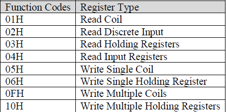
Table 1: MODBUS Function Codes

Figure 3: RTU Message Frame.
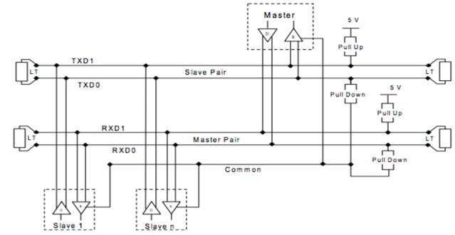
MODBUS can be set in either simplex or duplex mode depending on the physical wiring arrangement at the port. In simplex mode or 2 wire bus, only one device is able to transmit at a time. In full duplex mode or 4 wire MODBUS, the master receives slave data on the slave pair and transmits data on the master pair which is then received by any of the slaves. [Figure 4] shows a typical 4W-MODBUS arrangement. The cable length is limited to the speed of the communication or the Baud Rate. For a Baud Rate of 9600 on a AWG26 or wider gauge cable, the maximum length of the cable is 1000m. The color coding recommended for each wire are the following, for TXD0 – brown, TXD1 – yellow, RXD0 – white, RXD1 – blue, and Common –
grey. MODBUS also specifies a visual diagnosis color LED indicator. For an active communication frame, there should be a yellow LED lit. For the case of an error a red LED is set and when the system is on standby a green LED should be used. This serves as a quick communication diagnostic tool for the operators.
Figure 4 General 4-wire Topology.