Micro-CT Scanning
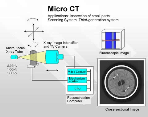
Micro-CT scanners use many of the same physical principles as traditional CT-scanners, but are engineered to accommodate smaller samples. Beginning at x-ray production, the x-ray vacuum tube contains a tungsten filament through which a user inputted current is passed. As the temperature of the tungsten increases, electrons are emitted and sent through a user-inputted voltage. X-rays are produced when the electrons decelerate in collisions with the target (anode) or with each other. Because of the variation in collision type, a distribution of xray energies is produced, with the maximum energy correlating to the input voltage. 99% of the energy in this process is converted to heat at the target, and 1% produces x-rays (“Fundamentals of X-ray Physics,” 2008). From the target, x-rays enter the chamber in a “cone beam” pattern. The specimen is placed on a rotating platform in the path of the cone. Depending on the ability of the specimen tissue components to absorb x-rays, some of the xrays are absorbed and some are allowed to pass. This phenomena is dependent not only on specimen components but on x-ray energies, as higher energy x-rays achieve a greater degree of penetrance through the sample. Transmitted x-rays hit a detector screen at the far end of the chamber. The detector is lined with a 1536×1920 array of charge-coupled devices that absorb photons and convert the energy to signal.
As the specimen lies in the beam, the platform it rests on is rotated in equal angular increments, with a “projection” image taken at each point.
Micro-CT Scanning
Projection images are similar to 2D radiographs, and are used to reconstruct the final 3D volume. After all projection images are acquired and the scan is completed, the projections are reconstructed into a 3D volume using a filtered back projection algorithm in the Nikon software package (Quiggin, 2011). In filtered back projection, composite projection images are considered to represent the volume in Radon Space, a coordinate space in which the function (i.e the object being scanned) is integrated over straight lines. In order to convert the object from radon space to its native object space, it takes a detour into Fourier space. A one-dimensional Fourier transform is taken of the object in Radon space, yielding the object in 2D Fourier space. The inverse Fourier transform is then taken to convert from 2D Fourier space to 2D object space, yielding the familiar CT crosssectional data. This transformation is validated through the Fourier Slice Theorem, which describes the relationship between an object in its Radon space and corresponding Fourier coordinates (“Two-Dimensional Fourier-Based Reconstruction Methods,” 2008).
