Voltage and Current Sensors
The bus connectors are connected to the voltage and current sensors which are designed for measuring all currents and voltages in the power grid. The voltage and current sensors are electronic transducers which are installed on the designed Printed Circuit Board
(PCB). The output of the sensors are connected to the DAQ cards and the voltage and current measured data can be read through the software platform for programming. Figure 2.6 shows the layout of the measurement board designed in the Dip Trace software and
Figure 2.7 shows the actual installed measurement board.
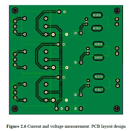
Figure 2.6 Current and voltage measurement: PCB layout design

Figure 2.7 Installed current and voltage measurement PCB
Optical Encoders
Optical encoder is a rotary encoder for measuring the speed and frequency of the generator. The optical encoder is mounted on the shaft of the generator and the output signals are send as a pulse data to the SCADA system for speed and frequency measurement. The obtained data is used for synchronization in the system. More detail
about the encoder and synchronization is discussed in the next section (software platform). Figure 2.8 shows a view of the encoder mounted on the shaft of the generator in the lab.
Figure 2.8 Optical encoder mounted on the shaft
Data Acquisition System (DAQ)
Data Acquisition (DAQ) system in the lab consists of two hardware parts: National Instruments (NI) shielded connector block (SCB) and NI PCI DAQ cards as shown in Figures 2.9 and 2.10. NI SCB as shown in Figure 2.9 is used for two main purposes. First, to send signals from measuring devices (like sensors, encoders etc.) to the NI Data Acquisition (DAQ) cards which are embedded in the central monitoring system. Second, to receive signals from the DAQ and sent them to the operating devices (like inverters, switches etc.) that are meant to receive control signals from the DAQ. Therefore, there is a two-way communication between the measuring and operating devices.
Figure 2.9 NI SCB 100-pin in the lab
Figure 2.10 DAQ hardware parts in the lab
Figure 2.11 Two-way communication architecture using DAQ in the lab
Figure 2.11 shows the two-way communication architecture implemented by the DAQ system in the lab for measurement and control purposes.
Switches and Relays
Relays
The electronic relays are used for switching operations, as shown in Figure 2.12. This set of switches are utilized for low voltage and low current operation and used for loads and transmission lines operation and control.
Generator Switch
Generators in the lab are equipped with two different switches: mechanical and electrical switches. The mechanical switch is mounted on top of the generator as shown in Figure 2.1. This switch mainly functions as a synchronization switch for the generator. The electrical switch is called as a solid state switch (relay). These switches are fully electronic switches that can withstand high currents and can be controlled automatically through the SCADA system. Figure 2.13 shows these switches mounted on the metal board inside the
rack.
Figure 2.12 Transmission lines relays and electronic switches
Figure 2.13 Generator electrical switch (solid state relay)
Bus Connector
The Bus Connectors are located at the back of the power rack as shown in Figure 2.14. The bus connectors make it possible for any type of power system configurations to be set up with the equipment and devices in the laboratory.
Figure 2.14 Bus connector rack