Heat Energy Collection Using Thermoelectric Device
In this post, we talk about Heat Energy Collection Using Thermoelectric Device.
The energy conversion is the fundamental aspect of the energy recycling. For instance, the electricity is generated by the kinetic or potential energy such as wind or waterfall. Heat, thermal energy is one of the natural and powerful energy that is beneficial and also critical element for human and living organisms. Moreover, the energy can be converted directly to electricity by using the thermoelectric device. The application of thermoelectric generation method is currently achieved with multi-disciplines from micro-sized biometric devices to a nuclear power source in space.
Functional Efficiency and Operational Factors
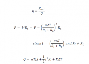
The thermoelectric device associated with any thermal power reusing system has two types of efficiency evaluation; device-wise and system-wise. For the device-wise efficiency, the main testing elements are the power conversion factors. Equation demonstrates the typical thermo-power device’s efficiency evaluation that is the ratio of the power output to the heat flow applied to the device. The thermal power, Q, is the input power generated by heat and its unit is Watts [W]. The heat is the main source of the electrical charges’ movement to generate the electrical current in the circuit. Thus, the strength of the Seebeck effect and the factors that represent the material’s reaction to the thermal power greatly influences the resulting power.
The major factors to select the adequate device for the system are the relative current density, U and the figure of merit, Z. The relative current density (U) indicates the ratio of the electrical current density (J) to the thermal conductivity (k) and temperature gradient (∇?). Since the electrical current is generated by the thermal flow, the Seebeck coefficient and temperature differences for each side of TEG device always affect to the amount of the current generated as shown in Equation . The electrical current flow is proportional to the thermoelectric sensitivity of a material (?) and the temperature difference (Δ?). Thus the higher relative current density can indicates the higher efficiency of the device. The figure of merit (Z) of the thermoelectric device is also an important factor to choose a device due to the relationship shown in Equation.The value of Z is defined by the thermal sensitivity which is strongly related to the material cost. The higher Z value can be achieved by the bigger gap between the thermo-power (same as the thermoelectric sensitivity,?) and the resistivity (?) of the device.

The device-wise efficiency is strictly related to the materials’ properties and their influences on the performance of the device. To choose the suitable device for the system, we must consider the system-wise aspect of power efficiency in the device selection also. The cost is one of the important factors in the device selection. It is the first priority for all system design projects. The higher material factors related to the device’s capacity increase the budget to build a device and a system. In the optimized design, the system-wise evaluation can help to reduce the cost of the device selection. The main purpose of this TEG using power supply is providing the required power with maximum power efficiency in the system. As shown in Figure , the device works like a DC battery with internal resistance. In general, the maximum power efficiency is achieved when the load resistor, R(L) is matched to the value of the internal resistor, R(in)).
The single TEG utilized in the circuit shown in Figure is a sample structure of a single cell in the TEG power generating system that contains four units of TEGs. Each unit generates the same amount of power ideally. They are combined in parallel and also in series to feed the power regulating circuit. The following equations show voltage and power output values from a single cell. V(L) represents the load voltage measured. V(NL) indicates the non-load voltage produced by a single cell TEG unit. The voltage produced from the unit can be calculated by using the voltage divider relationship shown on Equation . The maximum power output can be achieved when the load and the internal resistance are the same
defines the power efficiency is the ratio of the output power, P(o) to the input power, P(i) which is the thermal power, Q. This is a power efficiency based on the general concept of TEG device evaluation not related to the waste heat collection system. However, the actual power efficiency must be evaluated in the system-wise point of view. The SLHC system pursues the optimized TEG system that has free power source, passive heat sink, remoteness of the use-site and low noise solution due to the fundamental purpose of designing this system. This system uses the waste heat from the heater which meets the free power source requirement. Then, the input power becomes zero. Therefore, the normal power efficiency computed by Equation does not mean anything. Instead, the electrical power efficiency can be used for this evaluation procedure.
The electrical power efficiency is the ratio of the output power to the total power generated P(o) and consumed by the internal resistor R(i). For instance, the simple analysis of the efficiency can be analyzed by using the maximum power generating rule. Since the internal resistor is the same value of the load resistor, the expected efficiency is 50% . It could be not a practical value that can be expected because the actual efficiency is normally lower than the calculation due to the extra loss in the structural and operational procedure. However, it still refers a good range of device selection and the circuit designing options.