First Generation
The first generation CT scanners consisted of a dedicated head scanner with a water filled box. Pencil-width collimated beams of X-ray were used and these were detected on the opposite side using a single detector. The width of the X-ray beam was 3 mm within the plane of the image slice and 13 mm wide along the axis of the object (perpendicular to the slice). The X-ray source and the single element detector translate through the slice and rotate around the object with 1^ rotation steps, as show in figure1. A simple implementation of Algebraic Reconstruction Technique (ART) was used to reconstruct the cross-sectional images in the first generation.
Second Generation
The very long time to complete a scan was one of the most important concerns about the first generation CT systems. The scan time was reduced in the second generation with the use of multiple narrow beams and multiple detectors, in 1974. This scanner was the first waterless full-body CT scanner, that was introduced at Georgetown University . This device introduced several innovations which are still used in all CT scanners: table movement through the gantry, gantry tilting, and a laser indicator to position slices. A Fourier-based reconstruction algorithm was used to reconstruct the images in this scanner
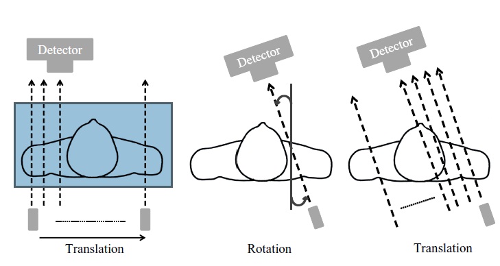
Figure1: First Generation of CT scanners which completed the scan in two repeated translation and rotation steps. Average scan time was about 6 min for one 360^rotation
and scan time was in the order of 5 to 6 minutes. As a result, patient motion was still a serious challenge in this generation. A second generation scanner with 3 narrow beams and 3 detectors is shown in Figure 2 (20 or more narrow beams and detectors were usually used in this generation).
nd , where nd is the number of detectors. Further speed improvements
were limited by the mechanical complexity of rotate and translate geometry. The mechanical tolerances and complexities involved indicated the need to eliminate translation motion.
Third Generation
Faster scans required the elimination of translation motion. This was achieved in third generation CT scanners that utilized a pure rotational motion by widening the X-ray beam into a fan beam to cover the entire patient width with an array of detectors, as shown in figure 2. To
have a sufficient number of measurements a large number of detector elements were used. The early third generation CT scanners, installed in late 1975, could scan in less than 5 sec. This generation, which is still used in the modern scanners, decreased the scan time to about 0.3
sec: modern slip ring design enables data to be transferred while the gantry is rotating. The most important problem in the third generation is called ring artifact. First and second
Figure 2: Second Generation of CT scanners which completed the scan task in two simultaneously repeated translation and rotation steps.
generation detectors were dynamically recalibrated at the beginning of each translation. In addition, each detector measures the rays passing through all voxels. Therefore, any detector error or drift was spread across the image evenly and was not visible. However, since in third
generation CT X-ray source and detectors move together, each detector measures rays passingn only at a specific distance from the center of rotation, depending on the location of the detector
in the array. As a result, any error or drift in the calibration of a detector is back projected along a ring, creating a ring artifact, as illustrated in figure 2-B. This problem has never been solved, but has been corrected by image processing algorithms in modern scanners.
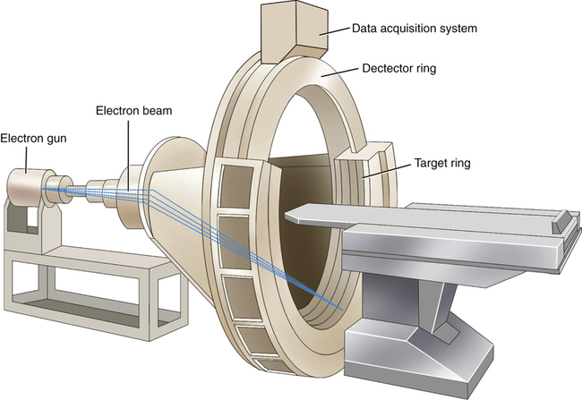
Fourth Generation
The fourth generation was designed to address the ring artifact in the third generation. It used a ring of stationary detector elements, as shown in figure 3. Unlike third generation detectors, each fourth generation detector can measure rays at any distance from the center of rotation and can be dynamically calibrated, so that ring artifact is not a problem anymore. However, many detectors were needed in this generation, which significantly increased the manufacturing cost.
Figure3: Fourth Generation of CT scanners with a 360^ detector ring.
https://tspace.library.utoronto.ca/handle/1807/69275