Wind Turbine Topologies
The variable speed wind turbines are commonly categorized into Indirect Drive Wind Turbines (IDWTs) and DDWTs. In IDWTs, the low-speed shaft is connected to the high-speed shaft through a gearbox, whereas DDWTs have a low-speed shaft that is directly connected to the generator . The two most commonly used topologies for wind turbines are based on Doubly Fed Induction Generator (DFIG) or Permanent Magnet Synchronous Generator (PMSG) . In DFIG configuration, the stator of the generator is directly connected to the grid while the rotor does not require to rotate at the fixed synchronous speed. The rotor is connected to the turbine shaft through a gearbox. In PMSG based wind turbines, the speed of the rotating magnetic field and the rotor is the same, and therefore, the generator must be connected to the grid through a power electronics interface. In other words, the PMSG based wind turbines require a power electronics interface to be connected to the grid which provides the flexibility of using these turbines with or without gearbox between the turbine shaft and the generator shaft . The commonly used topologies of IDWTs and DDWTs are discussed in the following. In IDWTs the rotor shaft is connected to the generator through a gearbox . These turbines have different topologies based on the type of generator and converter used for the wind power conversion. Figure 1.1 shows different topologies of IDWTs.
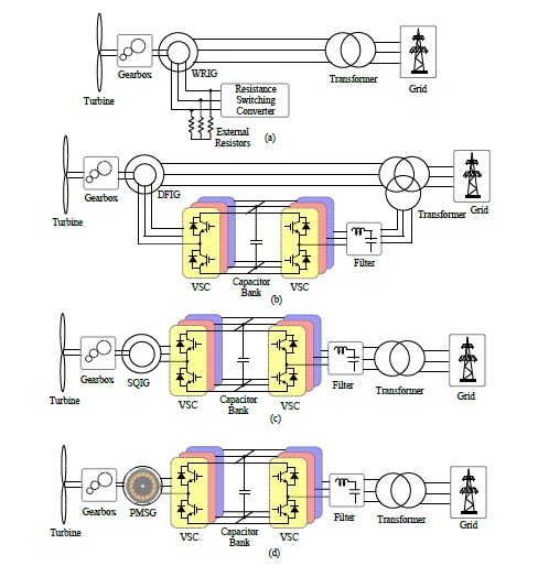
Fig. 1.1: Wind turbine system topologies for IDWTs with (a) WRIG and rotor resistance control, (b) DFIG with partly rated back-to-back VSCs for rotor connection to grid, (c) SQIG with fully rated back-to-back VSCs, and (d) PMSG with fully rated back-to-back VSCs.
Figure 1.1(a) shows an IDWT topology with a Wound Rotor Induction Generator (WRIG) with rotor resistance controller. In this topology, the output is controlled by varying the slip through variation in rotor resistance . This rotor resistance is varied using the converter. Figure 1.1(b) shows an IDWT topology with DFIG. In this system, the stator of the induction generator is connected directly to the grid and the rotor feeds power to the grid through the power electronic converters. The power electronic interface between the rotor and the grid comprises of a two bidirectional converters connected at the dc-bus, formed by electrolytic capacitors. In the system shown in Figure 1.1(b), the power converters are not rated for full power transfer and they share only a fraction of the power produced. Figure 1.1(c) shows an IDWT topology with squirrel cage induction generator connected to the power electronic interface, which comprises of the back-to-back Voltage Source Converters (VSC). Unlike the system in Figure 1.1(b) the power converters for this system are rated for the full power, i.e. the full power is transferred to grid through the converters. Figure 1.1(d) shows IDWT system with a PMSG and a back-to-back VSC as the power electronic interface. In addition to the previously mentioned topologies, IDWT with wound field synchronous generator can be used with back-to-back VSCs. In this type of IDWT, an additional ac-dc converter, powered from the grid is needed to energize the air-gap magnetic field of the generator. It has been shown that the gearbox causes more downtime than any other component in an indirect drive wind turbine . It is worth noting that, although gearboxes are responsible for 20% of total wind turbine downtime, they only account for 10% of wind turbine failures . Recent investigations reveal that gearboxes in wind turbines, which were supposed to last 20 years, might fail in 7-10 years . As a result, wind farm operators may face huge potential costs to fix their turbines in the near future. The solution to the problem is to get rid of the gearbox through the deployment of DDWTs .
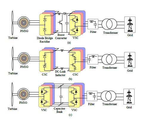
Fig. 1.2: Wind turbine system topologies for DDWTs with (a) PMSG connected to diodebridge, boost converter and VSI, (b) PMSG connected to back-to-back CSCs, and (c) PMSG connected to back-to-back VSCs.
In DDWTs, the turbine rotor shaft is directly connected to the generator shaft, and there is no gearbox employed. Figure 1.2 shows different topologies of DDWTs. Figure 1.2(a) shows a DDWT topology with a PMSG with the power electronics interface. The power electronic interface consists of a diode bridge rectifier, a dc-dc boost converter to stabilize the dc-bus voltage, and a VSI . The power electronics interface is rated for full power. Another DDWT topology is shown in Figure 1.2(b) with power electronics interface consisting of back-to-back connected Current Source Converters (CSC). The generator is a multi-pole PMSG. The dc-link between the CSCs has dc-link inductors in order to have a constant current input to the second CSC . Figure 1.2(c) shows the most frequently used configuration of DDWTs, comprising of PMSG connected to the grid through back-to-back connected VSCs . The dcbus between the VSCs is formed by electrolytic capacitors in order to have a stable and constant dc-bus voltage. In some cases, the power electronics interface can be a back-to-back connection of multilevel converters as discussed in the previous subsection. In some DDWT applications, a wound rotor synchronous generator is used . An additional ac-dc converter, which is powered by the grid, is needed to power the field of the generator. All the DDWTs discussed above either have a dc-bus formed by electrolytic capacitors or have a dc-link with inductors. The electrolytic capacitors are one of the most failure-prone components and decrease system reliability . The power electronics interface is one of the most vulnerable components in wind turbines , with the electrolytic capacitors known as the cause of more than 50% of failures . Many sophisticated methods which try to determine the remaining lifespan of electrolytic capacitors exist, but these methods do not serve to extend the life of the capacitors . The failure of these capacitors can have a huge impact on the system maintenance costs especially in the case of offshore wind turbines . The dclink inductors are bulky and add to the system loss reducing its efficiency . In some cases, the grid side converter located away from the wind turbine and the transmission cable is used to realize the dc-link inductor . Additionally, elimination of gearbox in the DDWTs leads to an increase in the size of PMSG, and thus, an increase in the capital cost of the overall system . The other major concern which prevents the popularization of DDWTs is the large size of the PM generator . The large size of the generator is a result of the generator shaft rotating at the same speed as the turbine rotor shaft. The number of poles in the PMSG for this configuration is very high to increase the frequency of the generator output voltage and current waveforms. The increase in the number of poles means increase in the PM material required. The PM material are rare earth metals which are expensive and the high number pf poles further results in increasing ye cost and volume of the generator.
