Power Electronics Interface Topologies
The incorporation of solid-state power converters in wind energy conversion systems has increased over the past decade in order to improve control of the wind turbine and to improve its interconnection issues with the grid . These power converters are also used to control the active and reactive power injected into the grid. The power converters used in wind energy conversion systems can be rated for full power transfer or for partial power transfer depending upon the type of wind turbine. In this subsection, the different configurations of three-phase power converters that are used in wind turbines are described.
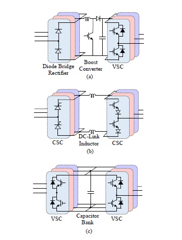
Fig. 1 : Commonly used three-phase two-level back-to-back power converter topologies for energy conversion in wind energy conversion systems.
The most common two-level power converter topologies used for three-phase power transfer are presented in Figure 1. Figure 1(a) presents a topology with a threephase diode bridge rectifier as the generator side converter which is cascaded with a boost dc-dc converter . These converters rectify the generator voltage and boost it to the desired dc-bus voltage. The dc-bus formed by electrolytic capacitors is then connected to a three-phase two-level VSC. The drawbacks of this converter topol-ogy is the distortion of the generator output current that results in the low-frequency torque pulsations at the generator shaft . Furthermore, the dc-bus is formed using electrolytic capacitors, which are the most failure prone component for any power converter . The next commonly used back-to-back converter topology used in wind energy conversion systems is shown in Figure 1(b). This topology is formed by a cascaded connection of Current Source Converters (CSCs), connected through dc-link inductors. This topology helps to eliminate the failure prone dc-bus capacitors but introduces another component, i.e. the dc-link inductors, which are bulky and contribute to losses in the system, reducing the overall system efficiency. The most commonly used two level back-to-back converter topology is presented in Figure 1(c). This topology is formed by a back-to-back connection of VSCs and electrolytic capacitors at the common dc-bus. This topology helps to eliminate the low-frequency torque pulsations at the generator shaft but still has the failure prone component. The topologies discussed so far are two-level power converters and when used for MW range of power conversion cause very high  stress at the generator and transformer, and would require bulky filters in order to reduce this high stress. For high power wind turbines (multi-MW power range), multilevel power converter topologies are used in wind energy conversion systems. Figure 2 shows the multilevel power converter topologies used in wind energy conversion systems. Figure 2 (a) shows a three-level Neutral-Point diode Clamped (NPC) back-to-back converter topology. This topology adds another voltage level as compared to the two-level topologies discussed earlier in this section. the multilevel structure helps in reducing the stress on the IGBTs and further aids in the reduction of the size of the output filter. Even though it is a very commonly used topology, the frequently failing capacitor bank still exists in this topology and its failure rate is high due to midpoint voltage fluctuation at the diode clamp . Another commonly used topology is the three-phase three-level H-bridge back-to-back converters shown in Figure 2(b).
Fig. 2 : Commonly used three-phase multilevel back-to-back power converter topologies for energy conversion in wind energy conversion systems.
This topology eliminates the problems of dc-bus midpoint voltage fluctuations and has smaller dc-bus capacitors as compared to the NPC topology, but still employs the failure prone electrolytic capacitors to from the dc-bus. Another power converter topology is five-level NPC converter, formed by back-to-back connected fivelevel NPC converter which is connected at the dc-bus formed by electrolytic capacitors . Similarly, back-to-back connected five-level H-bridge converters are also used in wind energy conversion systems . Some wind turbines also use the back-to-back connection of a three-level NPC converter and a five-level H-bridge converter, connected at the dc-bus formed by electrolytic capacitors . All the multilevel power converters used in wind turbines comprise of a dc-bus which is formed by electrolytic capacitors that adversely affects the system reliability and adds to the system operation and maintenance costs.