Distributed feedback (DFB) laser is the most widely used light source in optical communication systems. A DFB laser is a laser where the whole resonator consists of a periodic structure, which acts as a distributed reflector in the wavelength range of laser emission, and contains a gain medium. The device has multiple axial resonator modes, but only one mode stands out of mode competition for it is favored in terms of losses. Therefore, single-frequency operation is often easily achieved, despite spatial hole burning due to the standing-wave pattern in the gain medium.
Kogelnik and Shank first investigated in their paper the possibility of using a periodic structure within the laser medium to provide feedback for self-sustained laser oscillation . This possibility, discovered in 1971, was revolutionary because there is no need at the time to introduce cavity mirrors to the laser medium. Nevertheless, they demonstrated that such device is capable of good mode discrimination, and a single longitudinal mode operation is possible once the laser is locked to the oscillation condition.
The Optical modulation scheme is tested on 4 pieces of commercial DFB laser at 1550 nm, and the frequency variation of one DFB laser is significantly greater than the rest. After examining the frequency deviation of all four lasers under optical injection, one is found to have a frequency change significantly higher than the rest. Optical pump induced the switching between +1 and -1 mode in the DFB laser. In order to verify the true reason of this mode hopping, first the numerical model of DFB laser is studied and the spectrum of DFB laser is simulated.
There are two primary method to calculate the spectrum of DFB laser, coupled wave equation and transfer matrix method, and both them are used in the following discussions.
Coupled wave theory and transfer matrix method
Although the build-in grating structure is the most important feature that make DFB laser different from any other semiconductor laser source, analysis of Bragg grating doesn’t tell us everything we need to understand about the DFB laser, such as its longitudinal mode pattern, spontaneous emission spectrum, threshold current, linewidth, wavelength drift, etc. In this post, the numerical simulation is applied to analyze DFB laser in great detail, so as to provide us a powerful tool that is capable to predicting the laser behavior. Meanwhile some other variations in DFB structure are discussed as well.
The two most frequently cited approaches for modeling distributed feedback lasers are coupled wave theory, and layered-structure transfer-matrix theory. Both methods are satisfactory tools for predicting many characteristics of DFB lasers, though it has been shown that the transfer-matrix approach is slightly more accurate . A comparison between coupled mode theory, the Bloch wave approach, and transfer-matrix analysis is also given in [28], which concluded that the transfer-matrix approach is the simplest, most insightful and most accurate of the three models.
Often, the coupled wave theory is combined into transfer matrices, whereby a laser active region is broken into several large parts, each of which is represented by a coupled-wave transfer-matrix .
Simulated ASE Spectrum for Different Structures
The detail derivations of the coupled mode theory and transfer matrix method are given in Appendix A.
The parameter used for simulating a simple DFB structure is listed below
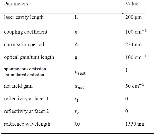
PARAMETERS USED FOR SIMULATION
The parameters are chosen to match a typical DFB laser diode with TO-can package with its emission wavelength centered at 1550 nm. For the simplest case, the information about corrugation is integrated into the coupling coefficient, and no surface phase or reflectivity is considered for now.
the DFB structure can be expressed by a single transfer matrix, and by solving the optical power versus different detuning factor, the amplified spontaneous emission spectrum of DFB laser can be estimated, which is plotted as below in Fig. 1,
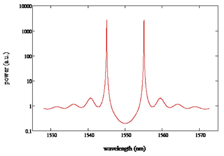
Figure 1. ASE spectrum of a uniform DFB structure with no facet reflection
With no oscillation found at the Bragg wavelength, a stop band region is formed between the t +1 and -1 modes of the conventional mirrorless DFB LD. It is clear since no influence is introduced to break the symmetry; the two strongest modes are identical to each other. Then the spectrum is plotted versus different gain, as indicated in Fig. 2.

Figure 2 ASE spectrum at different optical gain (in the unit of gain×Length)
In Fig. 2 we can see the output power is plotted versus wavelength at different optical gain, which is nondimensionalized by multiplying the length of laser device. It shows that the base line of spontaneous emission is growing with gain, but the intensity of two dominant modes is clearly growing much faster than other modes. After reaching threshold, one of these two modes will start lasing and hence suppress the other. However, in a purely symmetrical configuration, these two modes have equal opportunity to become dominant, and that is not desirable in practical application.