Networked MODBUS Transmission Control Protocol (TCP) CONTROL SYSTEM SETUP
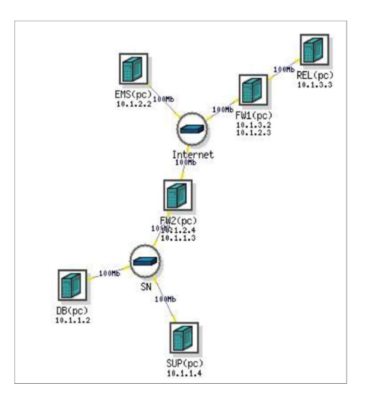
Figure 1 . DeterLab Topology for Cyber-Robust System
The experiment is set up with a Modbus networked primary controller and supervisor computer represented by Raspberry Pi mini-computers both connected to a network switch using LAN cables. The primary controller is hardwired to the sensor (DIP switch) and an actuator (LED), it also has a LAN interface (192.168.0.3). The secondary controller is represented by a programmed Arduino board which is network isolated and hardwired to perform the same functions as the primary controller by connecting to the sensor and actuator. Both the primary controller and the secondary controller send their control output signals to the supervisor computer. The supervisor computer monitors both control output from the primary controller and the secondary controller along with the sensor output. If the primary control output is accurate then the supervisor computer allows the control output of the primary controller to be sent to the actuator. If the primary control output is not accurate then it switches control to the isolated secondary controller by allowing the control output of the secondary controller to be sent to the
actuator.
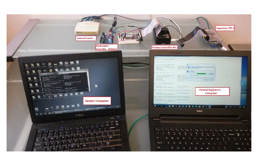
Figure 2. Experimental Set-up
The network server is a laptop computer running Microsoft Windows operating system with the LAN interface connected via LAN cable to the Modbus control network (192.168.0.9) and the Wireless LAN adapter interface connected the Howard University Wi-Fi network (10.232.100.32). The remote Energy Management System is represented by another Windows based laptop connected to the Howard Wi-Fi network (10.232.100.86). The control system network environment and hardware architecture used in the experimentation is illustrated using Figure 1.

Figure 3. Schematics of Hardware Experimentation
The firewall rules of the supervisor are configured to send a unidirectional alert message via Simple Network Management (SNMP) protocol to the EMS if an intruder is detected. The field sensor is represented by a DIP switch. Changing the toggle position simulates a range of conditions from the field sensor device. The sensor is physically connected to both the primary and secondary controllers as well as the supervisor computer. The LEDs give a visual indication when a fail-safe condition is present and the supervisor switches to the redundant controller. An email notification is simultaneously generated and sent to the remote EMS. The command for actuation is given only after comparing the controller signals against the database. Snort is hosted on the supervisor computer and is the software used for Modbus control data bus monitoring and intrusion detection on the network. The staged cyber-attacks are performed by an internal intruder using the manager’s credentials to log into an engineering workstation and an external intruder using an external IP address to connect remotely into the system for both the operational based and improved intrusion detection architectures.
Staged attack on operational based system
Internal Attack
The hacker acquires the credentials of the manager’s computer and uses the built in Windows Remote Desktop application to successfully remote to the network server using the IP address 10.232.100.32. The hacker then launches another Remote Desktop connection and uses the IP address to connect to the primary controller (192.168.0.2). The hacker enters the credentials and gains access to the application used to modify the settings of the primary controller. The hacker creates two
scenarios:
1. Make a significant change to the controller which causes the supervisor to quickly detect a discrepancy and switch to the operation-based control by disabling the primary controller and switching control to the secondary Arduino controller.
2. The intruder accesses the network and makes an extremely small or no change at all to the controller such that the intrusion is not detected by the supervisor. The primary controller remains active however the small change could eventually cause significant damage to the physical process operation and allows the attacker to carryout reconnaissance remaining undetected on the network.
External attack
The intruder uses an external IP address to get onto the network server via the internet. The hacker carries out the same two scenarios for an external attack and gets the same results. The experiment illustrates the vulnerability of the existing system and the potential safety-threats if the control system is meant for a critical application such as a safety-system or nuclear plant
reactor.
Figure 4. Attacker gains access to the Control Engineer’s computer
The attacker creates a RDP connection from the Control Engineer’s computer to the Modbus Master and executes Modbus function code 3 which is a “Read multiple registers” command on a controller device with Modbus Unit ID 0 reads the settings in the first 3 registers .
Figure 5. Modbus Function Code 3 – Read Multiple registers
A read registers command of the current controller settings is undetectable in the present system and is not noticeable hence the redundant controller is not activated. The intruder is not detected and hence can launch an attack at any time.
Figure 6. No detection or verification of a Hacker on the network