Inertial Systems
Inertial motion capture systems use miniature sensors and sensor fusion algorithms. Oftentimes, prototypes for these systems include accelerometers, gyroscopes, and magnetometers. In most cases, the data are transmitted wirelessly to a computer where they are recorded or viewed.
Accelerometers measure proper acceleration (as opposed to coordinate acceleration, which is expressed as the rate of change of velocity, and depends on the coordinate system or observer).
For example, an accelerometer at rest will measure an acceleration of 9.8m/s2, while an accelerometer in free fall will measure zero acceleration. An alternative to optical and force plate systems, accelerometers have been widely used in gait analysis. They have been implemented in shock absorption studies, gait parameter analysis (including FC), age-related changes in gait [30], and studies to determine the risk of falling in special populations. The main problems when working with accelerometers are their susceptibility to vibrations, which have to be filtered out, and the compounded drift that appears when integrating the acceleration signal to obtain speed or displacement.
Gyroscopes measure angular velocity. Gyroscopes make it possible to measure orientation and rotation after taking into account the sensor’s initial condition. A downside of gyroscopes is the drift that accumulates on them. However, this drift can be neutralized when information from accelerometers and gyroscopes can be processed together, allowing systems that measure displacement to be more robust and reliable; this is why “sensor fusion” is so popular in building inertial systems.
Benefits of using inertial systems include their low cost, compared to OMCS used in gait laboratories; the unrestricted mobility of the participants, due to the small size of the instruments, wireless capabilities that can be built into them, the possibility of powering the system with batteries and the resulting system’s portability because of the reduced weight. Nevertheless, they have disadvantages: lower accuracy, compared to OMCS; and positional drift, which compounds over time due to the accumulated error from the various sensors implemented as well as the algorithm used in calculating the data.
The literature shows extensive use of inertial systems in gait analysis studies. One of the first reported attempts to use inertial systems to measure spatiotemporal gait parameters was Aminian et al.’s 2002 study. In that study, an ambulatory system was designed to record heel strike and toe-off data during long periods of walking using a gyroscope. The recordings were then processed and compared to the readings from foot pressure sensors. This effort achieved small error and strong correlation values (coefficient of correlation (r) > 0.9 and root mean standard error (RMSE) = 23 ms).
Following in these footsteps, the team headed by Sabatini developed a portable system with a bi-axial accelerometer, one axis gyroscope, and two foot switches to estimate walking speed and incline. The inertial measurement unit (IMU) was mounted on the instep of the right foot. One of the foot switches was placed underneath the heel and another underneath the big toe, where it was taped to the foot. After obtaining the data, the team used Matlab to process the signals, obtaining a RMSE of less than 0.18 km/h (speed) and 1.52% (incline). Other teams have used IMUs to assess stride length and foot placement. Schepers et al. wanted an option to the optical systems traditionally used, and developed an instrumented shoe that collected data from the accelerometer and gyroscope. Data were postprocessed (double and single integration respectively). This method was able to calculate the stride length with an RMSE ± standard deviation (STD) of 34.1 ± 2.7 mm and a foot placement of 6.5 ± 1 mm.
In terms of the use of IMUs for detection of FC, a study by Greene et al. investigated the clinical relevance of inertial sensor-derived parameters. It successfully used triaxial accelerometers and triaxial gyroscopes to capture a 30 meter continuous walk; data were then transmitted via Bluetooth for subsequent offline analysis using Matlab. The inertial sensors were mounted on the shank of 114 community dwelling elderly adults, with and without a history of falls. Parameters based on the shank angular velocity signals that were shown to be associated with FC showed significant differences between fallers and non-fallers. The study concluded that angular velocity is an important parameter in falls risk in steady state walking.
Benoit Mariani has led two different studies to validate the use of IMUs for obtaining FC data. In, after transmitting wirelessly, raw values were preliminarily processed to extrapolate some missing data. Then the system computed stride length, stride velocity, FC, and turning angle parameters. Accuracy and precision of the proposed system were compared to an OMCS as reference. A mean accuracy ± precision was obtained of 1.9 ± 2.0 cm for FC. Moreover, in new 2D and 3D kinematic models were developed and validated against an optical system. Sensor measurements were saved on an SD card and then transferred to a computer for
postprocessing. The best absolute accuracy and precision (expressed as the mean ± STD of the set of difference with the reference system) were observed for MinFC, with 0.4 ± 12.6 mm and −12.7 ± 9.1 mm, respectively, for the 2D and 3D models. Although accuracy (mean) was lower for the 3D model, precision (STD) increased when compared to the 2D model.
Additionally, a recent study by Santhiranayagam et al. proposed a technique to estimate FC parameters using data from inertial sensors (accelerometers and gyroscopes). Fifteen features were extracted from raw inertial sensor measurements, and a general regression neural network model was used to estimate two key FC parameters, which were then compared to the measurements obtained by an OMCS (Optotrak®). Participants walked on a treadmill at four different speeds, wearing inertial sensors and the optical system’s reflective markers. After comparing, the RMSE was 4.04 mm, a promising result for calculating FC, although the algorithm would have to be implemented on-chip in order to make the full prototype portable.
Similar to the previous study, regression models have been applied to inertial sensor-derived variables to estimate the mean FC, and then compared to the values obtained by the OMCS in the study by McGrath et al. Inertial sensors were located on the foot and shank of the participants. Pearson correlation coefficients were stronger on the foot measurements, and the largest mean correlation coefficient with mean FC (calculated across all subjects) was found between the mean absolute-valued vertical angular velocity derived from foot-mounted inertial sensors (left, r = 0.77; right, r = 0.72).
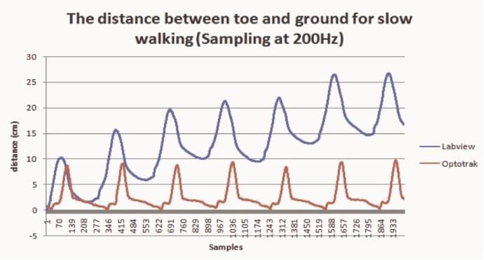
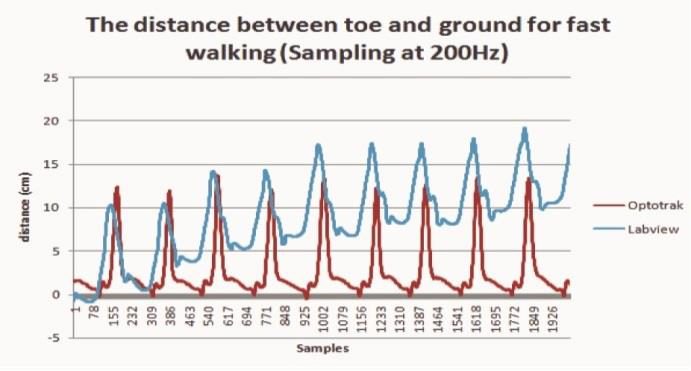
Lai et al. designed a prototype of a wireless device for monitoring vertical FC. The sensors consisted of a triple-axis accelerometer and dual-axis gyroscope connected to crossbow sensor motes for wireless data transmission. Significantly, this was the first noted attempt to achieve a real-time output through a graphic user interface (GUI). The team compared the calculated FC against measurements made by an Optotrak® system, and although the calculated values followed the trend set by the OMCS, the drift that the prototype induced on the measurements made calculating correlation or accuracy values impossible. Thus it was concluded that the system could be further improved.

Figure 1. Signals obtained by Lai et al. showing drift over time

Figure 1. Signals obtained by Lai et al. showing drift over time
Other Systems
A number of other transducers and technologies have been explored to try to obtain different gait parameters for their study.
Ultrasound Sensors
Like IMUs, ultrasound sensors have been adopted by several groups and laboratories when it comes to measuring FC and other gait parameters. In some cases, such as in, standalone ultrasound sensors were implemented; no other sensors fed the system. In their study, Bakar et al. focused on designing a portable, shoe-integrated, wireless microelectromechanical system (MEMS) FC measurement system. Although the study did not compare the system measurements to any reference like an OMCS, the designed prototype offered an advantage over IMUs: ultrasound sensors can read the distance between the foot and the ground, reporting the real FC, while IMUs calculate this value under the assumption that the ground level is always uniform and no obstacles appear under the foot. However, ultrasound sensors present their own set of limitations and disadvantages. They cost more than IMUs and have measurement limitations—some will start measuring after a minimum distance of 4 cm has been set between the sensor and the ground, which falls within the range of average FC.
Mixed Systems
Some researchers have worked with systems combining several types of sensors, looking for better accuracy and an improved system. Bamberg et al. developed the GaitShoe, which uses three orthogonal accelerometers, three orthogonal gyroscopes, four force sensors, two bidirectional bend sensors, two dynamic pressure sensors, and electric field height sensors. The pitch, displacement, heel-strike and toe-off timing as analyzed by the prototype system were compared to data collected from a traditional OMCS. The GaitShoe proved highly capable of detecting heel-strike and toe-off, as well as estimating foot orientation and position. The team concluded that portable, wearable systems offer the benefit of providing gait evaluation over longer periods of time versus the limitation of a one-time visit to a motion laboratory. The need to evolve into a real time system was stated.
Wahab et al. also developed a hybrid system using IMUs, ultrasonic sensors, a piezoceramic sensors array, XBee wireless modules, and an Arduino processing unit. Although the team was able to obtain real time measurements, accuracy was not estimated and the system was not compared to any reference like an OMCS.

