Since the ultimate goal is to achieve customized two dimensional sweeping in the I-v plan, eventually frequency chirp must be measured and calibrated. In this post, the causes and consequences of frequency chirp are discussed, as well as different methods to measure the frequency chirp.
Frequency chirping of directly modulated semiconductor laser in interaction with chromatic dispersion causes distortions of the signal travelling along the optical fiber. These distortions are the main factors limiting the bit rate in medium and long-haul transmission systems based on standard single-mode fiber in 1.55 μm window, displayed in Fig. 1. In this wavelength range, the absorption is minimized (about 0.17 dB/km ), and the typical dispersion coefficient for standard SMF-28 is around 17 ps/nm-km .
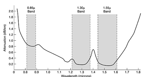
Figure 1. Optical wavelength windows used for communication
Here, strong dispersive broadening of modulated signals can occur in cases with high data rates. Without dispersion compensation, each symbol would be broadened so much that it would strongly overlap with a number of neighbored symbols, as indicated in Fig. 2.
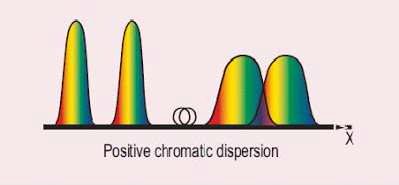
Figure 2. Broadening of optical pulse caused by chromatic dispersion
Even for moderate broadening, significant inter-symbol interference can strongly distort the detected signal [45]. Therefore, it is essential to compensate the dispersion before detecting the signal.
Zero chromatic dispersion is not necessarily ideal for data transmission. Particularly for the transmission of multiple channels, four wave mixing effects can be phase-matched and thus introduce significant distortions [46], if the dispersion is too weak. Various methods to overcome this limit were developed and widely used in wide area networks (WANs). In general, the laser chirp may be eliminated by applying the external modulator , or the dispersion may be reduced (compensated) , or the transmission span may be divided by regenerators into the shorter ones . Either one of these methods increases the complexity of the system as well as the cost. The chirp free intensity modulator cost approximate 1500 dollar each, which is much less attractive comparing to phase shift keying, who uses the same kind of device but is capable of significantly increasing the bit rate.
The second method is using Dispersion Shifted Fiber (DSF) . Unlike regular single mode fiber, DSF has a negative dispersion coefficient, which is achieved by modifying the refractive index profile of the core. Common index profiles of dispersion-shifted fibers have a triangular, trapezoidal or Gaussian shape. The typical dispersion coefficient of DSF is around – 100 ps/nm/km; in another word, the chromatic dispersion of a 100 km length of standard fiber operation at 1550 nm can be compensated by connecting it to 17 km of shifted fiber.
In a WDM system it is quite hard to balance dispersive properties of fibers in this way. This is because the range over which the WDM signals are spread may be of the order of 30 or 40 nm. The dispersion characteristics of each fiber used will be different at different points over the wavelength range. Matching dispersion characteristics over a range of wavelengths can be very difficult. This may well result in one channel of the WDM spectrum having zero dispersion (total at the end of the link) and other channels having significant finite dispersion.
Coupling between Intensity and Phase
As early as 1958, even before the invention of first laser, Schawlow and Townes calculated the fundamental (quantum) limit for the linewidth of a laser , which is given as

with the photon energy ![]() , the resonator bandwidth (half width at half-maximum, HWHM), and the output power . It has been assumed that there are no parasitic cavity losses. Note that the result is interpreted as a half width at half-maximum.
, the resonator bandwidth (half width at half-maximum, HWHM), and the output power . It has been assumed that there are no parasitic cavity losses. Note that the result is interpreted as a half width at half-maximum.
The first careful measurements of the linewidth of an AlGaAs injection laser versus optical power were reported by Fleming and Mooradian. They found the spectrum to be Lorentzian in shape, with a full width at half intensity that varied inversely with output power . These features have also been established for gas lasers and are expected for lasers in general . Surprisingly, however, they reported that at 300 K the magnitude of wasabout 50 times greater than they had expected according toconventional theories of semiconductor laser linewidth.
In 1981, Professor Charles H. Henry first introduced the linewidth enhancement factor α, which explained the broadened laser linewidth comparing to its quantum limit. In general, the width of the laser line can be thought of as due to fluctuations in the phase of the optical field. These fluctuations arise from spontaneous emission events which discontinuously alter the phase and intensity of the lasing field.
Besides the instantaneous phase change caused by spontaneous emission, there will be a delayed phase change resulting from the instantaneous change in field intensity. To restore the steadystate field intensity, the laser will undergo relaxation oscillations, which last about 1 ns. During this time, there will be a net gain change,
where An”(t)is the deviation of the imaginary part of the refractive index from its steady-state value. The change in n” is caused by a change in carrier density, which will also alter the real part of the refractive index n’. The ratio of these changes is
A change in Δn′ during a limited period of time results in an additional phase shift of the laser field and in additional line broadening. The linewidth of the laser should be increased by the factor , which turned out to be in reasonable agreement with experimental data.
It shall be noticed that in above definition the linewidth enhancement factor is independent of the spatial distribution of the carrier density modulation, such as the incomplete carrier pinning in the side wings of the optical mode.