The fog architecture – from atom to Adam
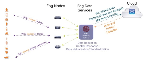
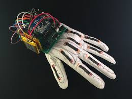
As we further our discussion on the fog architecture, it is instructive to consider the whole picture. The goal of fog is to minimize the latency of the reaction of an application. It seems appropriate, then, to examine the flow of information, from atom to Adam the user. The thing device sensing, the edge node filtering and relaying, the fog orchestrating analytics and data flow, the cloud developing deeper insights, all tied to the user whom the technology is designed for play roles in the design considerations of a fog platform. As the hardware for technology becomes geometrically smaller and lower in power consumption, a door opens to new, previously impractical use cases. Following this trend is the increased intimacy technology can maintain with its user, particularly in the case of new, wearable technology. In this light, we will discuss the components involved through the lens of WearUP, an electronic textile smart glove system designed for PD. As mentioned earlier, we have carefully designed experiments on WearUP to test its repeatability, precision, and sensitivity in quantifying the motor symptoms present in the finger tapping task. WearUP was tested using a robotic hand programmed to make precise finger tapping movements.
The fog architecture
Smart Glove as a Thing device – Flex Sensors, Inertial Motion Units, and Microphones:
This information is at the tip of your finger, literally. The concern is reliably and accurately collecting all the relevant information. We need to understand how the hand is positioned in space. This requires knowing the relative spatial orientation of the fingers and palm. The glove uses single angle flex sensors and inertial motion units (IMU). So what are these devices and what do they provide for the application? The things used in the testbed perform a variety of measures and are tied to applications that require the derived data points to be accurate and transported appropriately. The first thing device is a set of Flex Sensors tied to a glove in a application called WearUp. The flex sensors used are in essence variable resistors using conductive ink that increases in resistance as their surface area increases. These are placed between two flexible conductive traces housed in a clear insulative material. The resistance when flat is roughly 20kΩ and when bent to a 90° angle increases to roughly 70kΩ. Measuring this physical state requires a static state for comparison. We create this static state by introducing standard resistor. To measure the relative change in state between the standard resistor and flex sensor, we design a simple voltage divider. This allows us to extrapolate the desired information using Ohm’s Law. A final consideration for this set up is to maximize the voltage range to increase the signal to noise ratio. We chose to use a standard 10kΩ resistor, which provides a potential voltage swing of approximately 1v. Later, we mapped this range from 0 to 1024 as the flex sensors resistance reaches its maximum at a 90° angle. Along with measuring the flex for each finger, we needed to quantify the movement of the hand. We do this using an inertial motion unit (IMU). This device is found in many handheld devices, including smartphones. This device measures the hand’s acceleration, orientation, and direction. It exploits physical phenomena and converts that into digital values. The accelerometer uses Newton’s first law “An object at rest will remain at rest unless acted on by an unbalanced force.
Smart Glove
An object in motion continues in motion with the same speed and in the same direction unless acted upon by an unbalanced force”. This is also known as the law of inertia. A thought experiment of a ball resting on a plate can help illustrate the physics of the accelerometer. The gyroscope has a varying geometry but uses a reference point to maintain a “level” plane. The angular changes in the device’s current orientation and the “level” plane help us identify tilt. Whereas, the magnetometer measures the magnetic field and uses that to derive a sense of direction. Our gloves use the LSM9DS1 set to provide a linear acceleration full scale of ±8g, a magnetic field full scale of ±8 gauss and an angular rate of ±500 dps. We set the sample rate to 250Hz. This data is initially stored as an unsigned 16-bit integer. These same values are passed directly to the Bluetooth payload. One concern in design for the glove is this passing of information. The IMU communicates serially so the wires connecting the IMU to the Bluetooth device need the bandwidth for a clock. The MCU must be small enough to fit on the back of a hand, consume very little power such that the battery life of the glove extends beyond one practice session, and
have the processing power to compute the simple mapping of the analog to angular values at close to real-time speeds. Currently, the MCU being used meets those requirements and implements extra high-frequency filtering to reduce false readings.
Edge device – Intel Curie-Based, Low-Power Embedded System
The edge device of interest is a microcontroller unit (MCU) used in a pair of smart gloves for the WearUp application. It must be small enough to fit on the back of the hand, consume minimal power so the glove’s battery life extends beyond one practice
session, and have the processing power to map the analog values to angular values in near real time. Arduino 101, the currently implemented MCU, meets these requirements. The Arduino 101 is a learning and development board which contains an Intel Curie Module. This board is designed to integrate the Curie’s low power-consumption and high performance with the Arduino’s ease-of-use. The Arduino 101 also provides 19 channel 12-bit ADCs, Bluetooth Low Energy capabilities, and power management circuitry to ensure stability in reference to analog readings. Once the glove is paired with a Bluetooth device, it begins to capture angular values from the finger flex sensors and store them as unsigned 8 bit integers in a first in, first out (FIFO) array. Once this array is filled, it is sent over an available BLE connection using the standardized GATT UART Service. This service provides the name, sensor location, and control points of the detecting device. An instance of the GATT UART Service can be updated by calling the object’s notification function. This function is defined in the GATT UART Service header. Updating objects through functions is the standard method in BLE libraries. Once the object is updated, changes will be transmitted to the paired device. The Smart Glove is always updating its local angular finger values with regard to a connected device. It is handled by an interrupt since requiring it to continue reading the values of the flex sensor without a paired device would waste power sampling unnecessarily.
