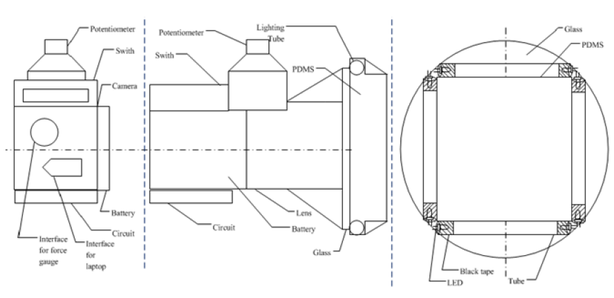
Figure 1: The Schematic of Final Design of TIS G2
Here is a list of the material we need to build second generation tactile imaging sensor.

Table 1 Material List for TIS G2
The frame of LED was made by glue (Arrow). First we used the glue gun to melt the glue stick and put glue around the LED tubes, and then used paper to shape the glue. For other components we placed all the parts around the camera and used super glue to hold them, then solder all the wire connection, then used black tape to wrap the sensor.
Other Possible Change
After finishing the main design of the TIS G2, there is one more upgrade planned in the future, the replacement of the force gauge. In our test, we continued using the force gauge Mark-10 M3 from TIS G1 system. The dimension of the gauge is 99 mm × 64 mm × 38 mm, we need to connect the gauge on the top of the TIS and hold the gauge to do the measurement. Also we need an extension interface between gauge and camera, which is not convenient. In the future design, we plan to use a small cell force sensor to replace this force gauge. The comparison of these two designs is shown below.
Figure 2: The Schematic of The Driving Circuit of the Light Source Unit
Test Plan of Second Generation TIS
The software used for image processing is Matlab. The graphical user interface (GUI) uses the MATLAB Image Acquisition Toolbox to create a link to the camera. The GUI connects the camera, sets up the camera variables, and starts the video feed automatically. The basic functionality of GUI is to be able to start and stop the camera, to view a snapshot or current tactile image of the processed video, and to save the current tactile image to specified folder.
In this design, we want to improve TIS with a larger contact area and clearer images. In the first test, we use white rubber ball as target. We press this ball use different regions of PDMS, and see if we can get clear image for all regions. The second test is to verify if this design can get clearer image and shape information of the targets. We use three targets with different shapes, a rubber ball, a rubber cube and rubber triangular prism to figure out if we can get clear shape information for the targets. Since the breast tumor is under the skin, in the third test we will determine if this device works for detecting the target under skin. We will use the inclusion phantom to perform indirect contact experiment. In this test, we will apply different force on the target and see the difference from the images between direct contact and indirect contact experiments.