Critical Infrastructure, Security Policies And Strategies
Critical infrastructure is a collection of systems and assets tangible and non-tangible that provides critical services (Fig. 1) to the nation and its protection must be addressed to ensure reliability and continuity to vital services in the health, energy, transportation, financial services and other sectors. In this chapter we will address the energy sector and evaluate the security aspects in the electrical smart-grids.
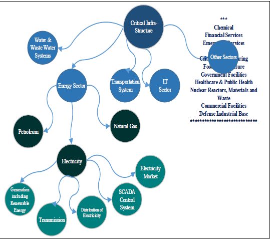
Figure 1 Critical Infrastructure – Energy Sector
Smart grid is made of several components including power plant’s generators, distribution, micro-grids, Remote Terminal Units (RTUs), Programmable Logic Controllers (PLCs) and smart meters located in the remote areas. Additionally, we have the control centers that are equipped with monitoring and control systems to oversee the entire operation of the smart grid.
Critical Infrastructure
According to the Department of Homeland Security (DHS), more than 80% of the US energy infrastructure is owned and operated by private sectors providing various kinds of energy sources including electricity, petroleum and natural gas to households and businesses. There are more than 6,400 power plants, 30,000 substations and 200,000 miles of transmission lines in the nation. Vulnerabilities in this sector exist that demands the proper balance between using security protection technologies and enforcing security policies and procedures to protect the nationwide assets. Reliability and business continuity is a must to critical infrastructures implementations and hence Cybersecurity is an essential aspect of this protection.
What is smart grid?
Smart-grid was initiated by National Institute of Standards and Technology (NIST) according to the American Recovery and Reinvestment Act (ARRA) in 2009 in order to establish intelligence and interoperability that incorporate smart technologies with various electricity distribution facilities and systems in order to improve reliability of the grids.
Smart grid is a digital technology of the electric grid that allows for two-way communication between the utility as the providers and the customer as the end-user. It is the collection of microgrids interconnected and linked to the SCADA operating at the control center. (Fig. 2), depicts a smart grid where each micro-grid has the capability of operating independently or as part of the smart grid. Disconnection and micro-grid isolation is possible in case of hazards or blackout.
Several measurement areas can be performed in each micro-grids including power conditioning, time synchronization, validation, metering and others.

Figure 2 Critical Infrastructure – Smart Grid
Smart-grid systems are complex environment that facilitate an improved and an efficient twoway path of communication and power handling capabilities. This involves the use of up to date technologies in areas such as power, communication, substations, smart meters and renewable energy resources in order to achieve highly secure, reliable, economic, and environmentally friendly electric power system. Smart-grid as a critical infrastructure involves both energy supply and demand and the deployment of smart meters is a requirement at the remote sites connected via wireless communication and the Internet and managed directly by SCADA monitoring and control system.
For monitoring and control, measurements data that are generated by various electronic devices are collected by the control center to ensure that measurements and control commands can be delivered to the proper destination within a few seconds or even a fraction of the second. The deployment of the Industrial Control System (ICS) enhanced the efficiency and reliability of power systems and the smart grid. There has been an integration of phasor measurement units (PMUs) with wide area measurement systems in addition to the installation of advanced metering infrastructures (AMIs) in the remote power systems. Next we will discuss the various components
of the smart grid that includes:
1. SCADA Environment
2. Remote Terminal Unit (RTU) and Programmable Logic Controller (PLC)
3. Energy and Distribution Monitoring System Software (EMS) & (DMS)
4. Phasor Measurement Units (PMU)
5. Substations with IED
6. Advanced Metering Infrastructure (AMI)
1. SCADA Environment:
SCADA operation and monitoring of the critical infrastructures has been deployed in various industries, such as power, oil and gas, transportation and manufacturing. In power sector, SCADA system can be used to collect measurements from remote sites and components of the power grid including current and voltage and the control data can be sent through the grid to regulate the circuit breakers. Data misbehavior can be detected and triggered by SCADA. Therefore, a quick responses is required to ensure data accuracy. SCADA system consists of both hardware and software units including sensors, control devices, communication system, human machine interface (HMI) in addition to EMS and DMS monitoring software.
2. RTU and PLC
SCADA data at remote sites is sent to the control center via Wide Area Network (WAN) links and then transported to the SCADA via Local Area Network (LAN) connectivity. Current and voltage sensors at the remote sites are connected to PLCs or RTUs. Remote terminal units (RTUs) are used for telemetry and programmable logic controllers (PLCs) are used to control devices and both can serve as data aggregators and a gateway to provide the connection necessary between electronic devices at remote sites and an the SCADA control system.
3. Software (EMS and DMS):
The software will be running at the control center to manage and monitor power system data related to both the transmission (supply) and the distribution (demand). Energy Monitoring System (EMS) provides functionalities, such as contingency analysis, state estimation and power flow optimization. On the other hand, the primary functionalities of DMS include acquiring customer data through smart meters in addition to outage or blackout management.
4. Phasor Measurement Unit (PMU):
PMUs are used to enable direct measurements of the voltage angles, initially was developed by Virginia Tech in 1988. PMUs have an extremely high sampling rate and synchronized to measure electrical quantities that allows for transmission system monitoring. The large amount of synchronized data can be used to improve the on-line monitoring of power system dynamics,
including voltage and transient stability. A phasor data concentrator (PDC), serving as a gateway, are installed in substations for collecting the PMU data in the phasor network and then the data is forwarded to the PDC in a control center. Vulnerabilities in phasor network exist and hackers can penetrated the network and monitor or inject false data. Since PMUs may use the Global Positioning System (GPS) for signaling, attackers can jam and spoof the GPS signals leading to operation instability.
5. Substations with Intelligent Electronic Devices (IED):
Substations are part of the smart grid infrastructure and they exist all the way between the power plant generators and the consumer. They provide voltage transformation from high-to-low or low-to-high in order to accommodate remote devices power requirements. Modern substations consist of intelligent electronic devices (IED) that provide the digital communication with a remote control center and merging units (MUs) and intelligent controllers. In addition to other complex circuits like protective relays, circuit breakers and switch relays. The implementation of IED improves the efficiency, reliability and security of power grid. They allow data that carry information to be transmitted to the control centers for processing and decision making.
6. Advanced Metering Infrastructure (AMI):
In smart grid environment, supplying power to consumers involves an advanced metering system. The provision of smart meters enhances the relationship between consumers and suppliers and the demand and supply complexity. Consumers can become a power generating entities if they are using solar panels or small wind generators that enables smart meters to record the energy flow from both directions. Smart meters are located at the customer premises that is a vulnerability for potential intrusion. Smart meters have intelligence and they are being integrated as part of the smart grid network. Since their function is to record the customer’s usage data, then the attacker can easily access the user’s private information and even perform theft to the electricity. A smart meter also serves as a controller and a router in a home area network (HAN). According to the Internet of Things (IoT), different appliances and devices can be linked to the Internet and the smart meter is an excellent example that can become as an IoT device.
Smart meters primarily use ZigBee wireless communication protocol an IEEE 802.15.4 standard and can be connected in a mesh network setup with Connected Grid Router (CGR) that is responsible for collecting meter readings and data from multiple neighboring smart meters.
Smart Meters at the end of the smart-grid network can use different protocols and standards to communicate with the master in the control center in a two-way communication adopting Advanced Metering Infrastructures (AMI). The threat of malware attack on the smart meter is very possible since it is exposed to the public and viruses or worms can spread rapidly in the AMI mesh topology. Therefore, there are a lot of research with respect to hardening the security of smart meters and AMI technology.
According to the Energy Sector Specific Plan, smart grids were initially modeled by NIST based on seven domains including customers, market, service providers, operations, generation, transmission and distribution. That is a collection of complex technologies working together for the purpose controlling demand and supply managed directly by SCADA.
Smart-Grid Communication Protocols
Smart-grid communication infrastructure is part of the energy sector that utilizes many SCADA internal and external protocols in delivering control messages and monitoring data across different part of the grid including IEDs, PMUs, AMIs and the control center. Such data potentially collected by PLCs and RTUs connected via sensors are being transported using one or more of the most popular SCADA protocols including MODBUS, DNP3, DNP3-SA and IEC61850 in addition to the ICCP acting as the inter-master communication protocol between the different micro grids. A brief description of SCADA popular protocols is provided as follows:
Modbus:
Modbus protocol is an industrial standard used extensively in the SCADA operations and is considered to be a popular one since its development back in 1979. Modbus protocol has two versions for packet transmissions; serial and TCP versions. The protocol defines function codes and the encoding scheme for transferring data as either single points (1-bit, coils) or as 16-bit data registers. This basic data packet is then encapsulated according to the protocol specifications for Modbus serial or TCP.
The TCP version of Modbus follows the OSI model and defines the presentation and application layers as a master/slave protocol, meaning a device operating as a master will poll one or more devices operating as a slave. The master will write data to a slave device’s registers, and read data from a slave device’s registers. A register address or register reference is always in the context of the slave’s registers.
Distributed Network Protocol Version 3 (DNP3) As discussed in chapter 1, DNP3 is an open standard that can be deployed using several topologies including point-to-point (one master and one outstation or slave), multi-drop topology (one or multiple masters and multiple outstations) or using the hierarchical layout where systems are arranged in a tree like setup and one outstation could act as both a slave to a DNP3 master or a master to other outstations. DNP3 messages can be mapped to the upper layers of the OSI model and are based on three layers including data link, transport and application layers.
Distributed Network Protocol is used in the communications between various types of data acquisition and control equipment as a master (SCADA) and slave (RTU) communication primarily in the utility industry including power, water, sewage, oil, gas and many other areas incorporating special sensors that will be attached to a data loggers unit acting as RTUs which in turns will communication with the master unit via DNP3. DNP3 is also used in communication between weather stations and can be used in road traffic controls, transportation, and many other applications.
The DNP3 data link frame consists of a fixed size 10 bytes long header block as “block 0”, then followed by 282 bytes long data portion divided into 16 bytes blocks and each block ends with two bytes as Cyclic Redundancy Check (CRC) code. There is one byte control field in the header. DNP3 will be explored later in more details.
IEC61850
Industry Electronics Commission (IEC61850) is one of the most recent protocols with the specification for the design and configuration of substation automation and it supports a comprehensive set of substation functions and rich features for substation communications.
IEC61850 uses a link-layer multicasting protocol Generic Object Oriented Substation Event (GOOSE) for transmitting timing-critical messages, such as substation events, commands and alarms, within the power substation networks. IEC61850 has the following features when running on IEDs:
LAN-based connectivity in a substation via Ethernet-based communication.
Enhancing interoperability, IEDs can import or export the substation configuration language (SCL) file, which contains device information. Using the auto-configured feature, IEDs from different vendors can be incorporated within the same substation without any compatibility issues.
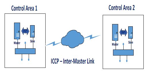
Inter-Control Center Communication Protocol (ICCP)
Inter-Control Center Communication protocol (ICCP) also known as the standard IEC60870-6 is one of the major smart-grid protocols used to interconnect masters from different micro-grids. ICCP can be used to meet the requirements for communication and co-ordination between multiple control centers. (Fig. 3), below shows a smart-grid using an ICCP link between two masters operating at separate control areas.
Figure 3 Smart-Grid Communication
The Internet paradigm, started in the mid-nineties, has played a major role in enabling the convergence between the conventional power grid and the smart technologies. Reliable information transfer between smart-grids components has become important to ensure performance, suitability, inter-operability and security. Therefore, we need to ensure smooth flow and secure transmission of traffic that will enable applications to manage power flow in the smart grid and to balance between the generation sources and the demands. Different assets sources and communication protocols are very important elements of the smart grid; over the years there has been tendency to standardize the protocols with enhanced security features.
I need matlab codes for communication protocols in smart grids