AUTOSAR – AUTomotive Open Systems ARchitecture
OEMs have the same language for their works.
OEMs have multiple suppliers in Tier1.
OEMS usually use same Tier1 for implementation of their functionalities.
using same language lead to that Tier1 can give services to multiple OEMs and OEMs can take services from different Tire1.
At now, the different vendors can give you different parts of an automobile software. similar to operating System that a game company can design a new game for our PC because the company knows the architecture of our operating system. In the automotive industry, the OEMs can give the software of autonomous driving to a vendor and the vendor design the software based on AUTOSAR.
http://www.erika-enterprise.com/
A fully Open-Source platform for automotive systems
If you design standard component you can sell to many companies.
Why do we need AUTOSAR?
Increasing the complexity of software in the automotive industry
There is no standard architecture.
Main drivers for AUTOSAR :
Management of electrical and electronic complexity associated with the growth in functional scope.
The flexibility of product modification, upgrade and update: We need to able to modify, upgrade, update the component of our software much easier than what was possible before.
If we have a way for easily mapping the same application on different hardware architecture then we can do our job with the low cost.
Software quality in the automotive industry is crucial because it will make difference between an accident or not.
AUTOSAR Software Components
AUTOSAR is based on the concept of separation between infrastructure and application. The software is running on the top ECU is composed of two elements :
Infrastructure: services providing an execution environment to abstract HW details. It runs the application.
Application: vehicle functions of interest. What the ECU shall do? It is the code.
Two are independent. We can design the application and infrastructure independently. It means that our application can run on different infrastructures.
OEMs can develop their own application and they do not want to share with the tier1 making the infrastructure. The tier1 is responsible for delivering just infrastructure.
Atomic software component:
A software component is a component that cannot be distributed over several ECUs.
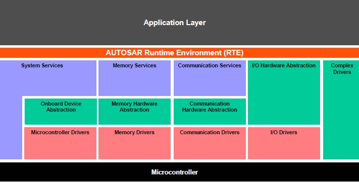
AUTOSAR architecture :

Basic software includes layers between RTE and Hardware. It is common to any AUTOSAR ECU. So if you implement an application for basic software you can use it in any ECU such as (Engine control unit, gearbox control unit, steering lock and so on). It is common to all ECUs.
In the Application layer, you implement custom functionality. For example, if you are doing an automatic gearbox control unit, the application layer can be for example implement the control of the dual clutch system using the standard basic software.
Microcontroller layer :
When you write a software, you do not want to know all the details of your microcontroller. You do not care specific resource of programming, for example, the Timer register, ADC, DAC, the type of interrupts and so on. These are too complex and they are too error-prone and make you waste a lot of time.
The microcontroller layer is to define an abstraction to the underlying hardware so the programming gets easier.
It is a set of function ( libraries ) that give you an easier access to the resources provided by the microcontroller. Every microcontroller has its specific microcontroller layer.
Silicon vendor implements the abstraction layer and this layer can be used for any basic software layer. silicon vendor can design it very good because it has complete knowledge about the microcontroller. They are implementing the function in a proper way.
ECU abstraction layer :
This layer is intended for delivering to the upper layer the ECU specific services. Multiple makers can implement the same services in multiple different ways. Form application point of view, we do not care.
This layer makes higher software layers independent of ECU hardware layout and Interfaces the drivers of Microcontroller Abstraction Layer.
Services layer :
This layer offers Memory Services, Diagnostic Services, ECU state management and Provides basic services for application and basic software modules.
AUTOSAR Runtime Environment (RTE) :
This layer is between the application layer and basic software. Makes AUTOSAR Software Components independent from the mapping to a specific ECU.
The AUTOSAR layer with more details has been shown in the following figure:
Application developer that worked in the automotive industry and used AUTOSAR, is responsible for modelling or coding portions of the application that called software component.
More experienced developer define the architecture and decide how many components you need to have and how they should communicate and so on.
Another developer can be responsible for implementing a single component.
Another job can be taking the specification of the application and configuring the runtime environment. It means defining how many components do you have and how they communicate.
An application in AUTOSAR is implemented as a number of components that interacts. The functionality that you have to implement. An application is made connecting different SW-C.
https://en.wikipedia.org/wiki/Commercial_off-the-shelf
Software Component contains a specific behaviour and interacts with other SW-Cs through a communication channel (Ports). The set of communication channel that your application uses is known as Virtual Functional Bus.
The application is designed independently from the infrastructure or execution platform. so when starting designing the application, you just focus on the plant that you want to control and the best controller that must be developed. Partitioning the software in the software components and making them interacting properly.
Example: A certain OEM tells you that you must deploy them on three different electronic control unit. Suppose three ECU in the following figure :
According to the resources available on these ECUs, You will decide that the first software component shall go on the first ECU. The SW-C 2 and SW-C 3 shall go on the second ECU and the final SW-C shall go on the final ECU. ECU 1 and ECU2 are connected through a vehicle bus and ECU3 in connected by a Gateway.
You must define the characteristics of each ECU such as how much memory you have, which communication channel you have available and so on.
As an application developer, you do not care about these details of the communication bus between ECUs or software components. You should not change your application to make it able to communicate through CAN network. Because the standard provided to you by AUTOSAR. The development tool does it automatically. SW-C2 and SW-C3 do not need CAN bus for data exchanging.
You can implement the application in one powerful ECU instead of three ECUs. The application developer does not change any things, the development tool will do other necessary settings for you based on this new ECU. In other words, deploying the same application on different hardware is in principle totally automated.
Consider a company that design algorithms for controlling diesel engine. It can support multiple types of engines. In Europe, four cylinders and in the US six cylinders. The infrastructure in different but the application is same. In AUTOSAR architecture, you can easily map the same application controlling the diesel engine on different infrastructure.
In Europe, the design is in diesel engine and in the US, the design is in the gasoline engine. They have the same components, so if you design in AUTOSAR architecture it is easy to map your application to different architecture.
A software component is atomic. It means you can map a single software component to a single ECU. You can not partition an SW-C and map it to different ECUs. An application can have multiple SW-C and SW-C can go to different ECUs but a single SW-C cannot go to multiple ECUs.
When you design architecture, you do not care how a software component will be implemented, you just concentrate on its functionality (Top level view). You look at the interfaces and communication among software components. You need the definition of ports in SW-C.
In PortInterface, you define how SW-C related with other software components or the operations and data elements that the software component provides and requires.
In the SW-C implementation, you define how the functionality of an SW-C actually is implemented.
Virtual function bus level :
An application is a composite of many software components. Software Components have communication with each other. At this level, the fundamental communication properties of components and their communication relationships
among each other are expressed.
example of a software component in a virtual functional bus level
There is a shape in the top of this figure. It is a black square. There many symbols for a software component that defines the functionality of a software component and has a specific meaning. Does it make some computation? If it has an interface with an actuator or a sensor.
AUTOSAR is a modeling language for modeling software. In here we can not simulate, we just interested in the architecture. so we can define the purpose of a software component and how to interact with other software components.
AUTOSAR supports multiple ways an SW-C can interact with other SW-Cs. So, you see there are many ports in the example SW-C. The shape of these symbols in a port specifies the property of the communication channel and port.
Input :
Passenger is sitting
Setting of the seat temperature
Information from a central power management system
Output:
DialLED associated to the seat temperature dial
Heating element
It can be calibrated, needs the status of the ECU on which the component runs and requires access to local non-volatile memory.
Port Interface
AUTOSAR has many communication protocols :
Client-server
Sender-receiver
Parameter Interface
Non volatile Data Interface
Trigger Interface
Mode Switch Interface
Client-server
There is a server that provides a service and there are multiple clients that can ask the service.
Sender-receiver
Data exchanges between SW-C.
A port of a component is either a PPort or a Rport :
PPort provides the elements defined in a port-interface
RPort requires the elements defined in a port-interface
Example :
We are going to design an application for the seat heater. Basically, you need some resistors on your seat, that you can warm up the seating. It mainly used when the outside of the car is cold and we make a comfortable state for the driver or passenger. A portion of this application looks like this :
SeatHeatingControl is an SW-C responsible for implementing the control algorithm.
SeatHeating is an SW-C works as sensor or actuator.
SeatHeating provides a service through a client-server port interface.
SeatHeatingControl requires this service (because the require port).
The detail of the service is shown in the interface block.
These SW-C (SeatHeatingControl , SeatHeating) can be in two different ECUs.
The driver seats a temperature for the seating and this setting sends by SeatHeating to the SeatHeatingControl to increase or decrease the temperature of the seating.
Example 2:
In this example, We want to warm up the seating when there is a person on it. There is a switch in the seating that has a connection with SeatSwitch software component. When there is a passenger on the seat, this SW-C send a data to SeatHeatingControl to detect that there is somebody on the seat.
We can have one sender and multiple receiver :
The specification of functional interfaces is divided into 6 domains:
– Body/Comfort
– Powertrain
– Chassis
– Safety
– Multimedia/Telematics
– Man-machine-interface
AUTOSAR SW-C
AUTOSAR SoftWare Components
Virtual Functional Functional Bus (VFB)
The AUTOSAR Software Component is an “Atomic Software Component”
Atomic means that each instance of an AUTOSAR Software Component is statically assigned to one ECU.
The AUTOSAR Interface can be
– Client-Server Interface defining a set of operations that can be invoked
– Sender-Receiver Interface, for data-oriented communication
A port can be
– PPort (provided interface)
– RPort (required interface)
In Client-Server interface
PPort: provides an implementation of the operations
RPort: invoke the operations
In Sender-Receiver interface :
PPort: generates the data
RPort: read the data
Client-server communication
The server is a provider and the client is a user of a service.
The client initiates the communication, requesting that the server performs a service, transferring a parameter set if necessary.
The server waits for incoming communication requests from a client, performs the requested service and dispatches a response to the client’s request.
The direction of initiation is used to categorize whether an AUTOSAR Software Component is a client or a server. A single component can be both a client and a server depending on the software realization.
Client-server communication
Sender-receiver communication
A sender distributes information to one or several receivers.
The sender just provides the information and the receivers decides autonomously when and how to use it.
It is the responsibility of the communication infrastructure to distribute the information.
The sender does not know the identity or the number of receivers.
Sender Receiver AUTOSAR
AUTOSAR Components, Interfaces and ports
AUTOSAR Components, Interfaces and ports
Sometimes, A component does not have any post, but all of the components usually have a port.
Virtual Function Bus (VFB)
The virtual functional bus is the abstraction of the AUTOSAR Software Components interconnections of the entire vehicle. The communication between different software components and between software components and its environment (e.g. hardware driver, OS, services, etc.) can be specified independently of any underlying hardware (e.g. communication system). The functionality of the VFB is provided by communication patterns.
AUTOSAR Runtime Environment
The RTE is the runtime representation of the Virtual Function Bus for a specific ECU.
The RTE provides a communication abstraction to AUTOSAR Software Components providing the same interface and services for inter-ECU (using CAN, LIN, Flexray, MOST, etc.) or intraECU communication.